Installing the CBX 500 Switch
Connecting External Clock Inputs and Outputs
Beta Draft Confidential
CBX 500 Multiservice WAN Switch Hardware Installation Guide 4/5/034-17
E1 Clock Connection
The E1 timing inputs work with E1 timing references that comply with the ITU-T
G.703, Section 6 standard. The E1 timing output takes its timing source from a
selected active SP clock source configured via the NMS.
The SPA panel also contains three 75-ohm BNC connectors for connection to:
• An external E1 clock input
• A redundant E1 clock input
• An E1 clock output
You can configure the operation mode (T1 or E1) through the NMS. For instructions,
see the B-STDX, CBX, and GX Switch Module Configuration Guide.
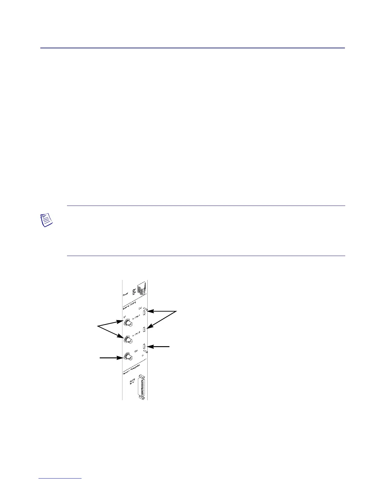
Figure 4-12 shows the location of the clock inputs/outputs on the SPA module.
Figure 4-12. External Clock Inputs and Clock Outputs
Note – Through the NMS software, you can configure the clock sources and
clock-source priorities. For example, you can adjust the line build-outs over a range of
0 to 655 feet for T1 timing outputs. You cannot adjust the line build-outs for E1 timing
outputs.
E1 Clock
Inputs
E1 Clock
Output
T1 Clock
Inputs
T1 Clock
Output
 Loading...

