Determining the Operating Status
Status LEDs
Beta Draft Confidential
5-44/5/03 CBX 500 Multiservice WAN Switch Hardware Installation Guide
During the boot process, which follows a cold boot or a power cycle, the Good/Failed
LEDs on the IOPs change states as described in Table 5-4:
Redundancy Status LEDs
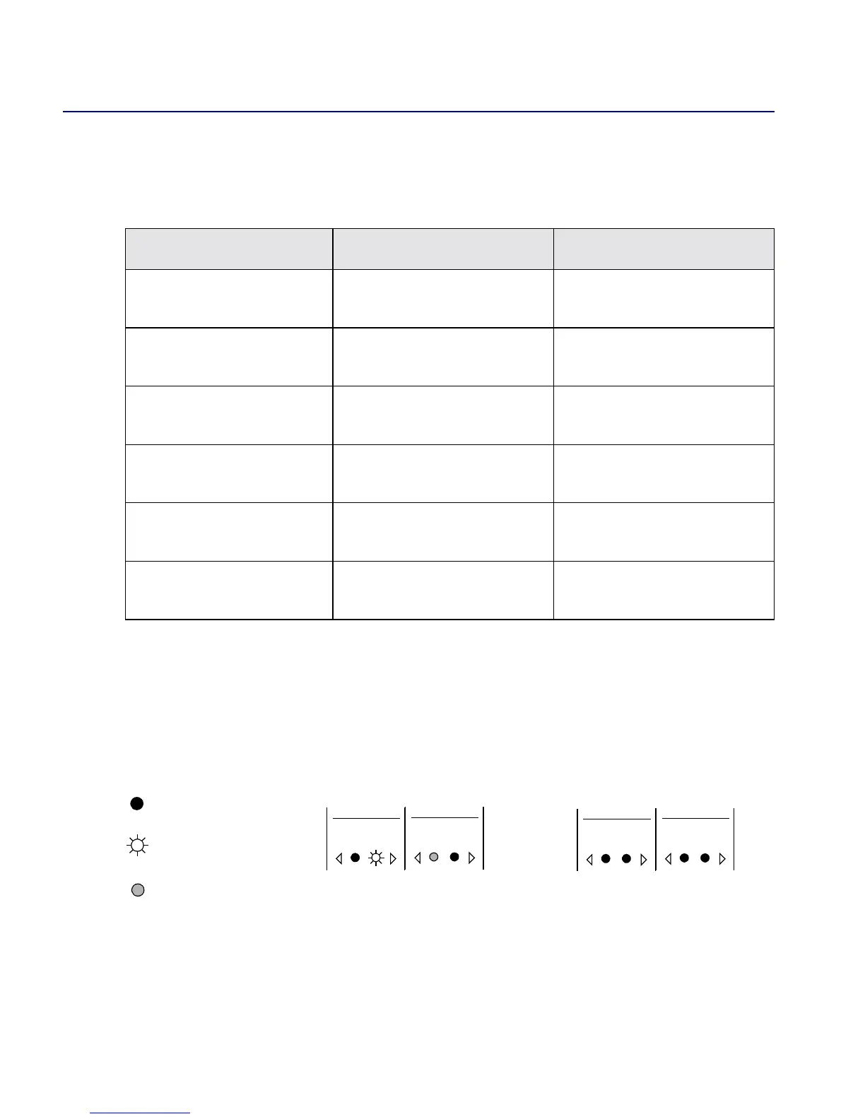
All modules have Redundancy LEDs on the bottom of the module to indicate the
redundancy status of the module. The LEDs are on, or blinking, only if the module is
part of a redundant pair.
Figure 5-1. Redundancy Status LEDs
Table 5-4. IOP LED “Boot” States
IOP State IOP Good (Green) LED IOP Failed (Red) LED
Extended POST failure OFF Blinking slowly, one second
ON, then one second OFF
Boot flash image update
from the hard disk
Continuously ON Blinking rapidly
Application image being
read from hard disk
ON/OFF at the same time as
Failed LED
ON/OFF at the same time as
the Good LED
Application image being
uncompressed
Blinking OFF
PRAM image being read
from hard disk
ON/OFF in sequence that
alternates with Failed LED
ON/OFF in sequence
alternating with Good LED
PRAM image being
uncompressed
Blinking OFF
Redundancy
Status
Redundancy
Status
=OFF
=ON
=BLINKING
Redundant Pair of Modules
Active
Module
Standby
Module
Redundancy
Status
Redundancy
Status
Non-Redundant Pair of Modules
 Loading...

