363-206-285
Power
4-2 Issue 3 June 2001
Power Description 4
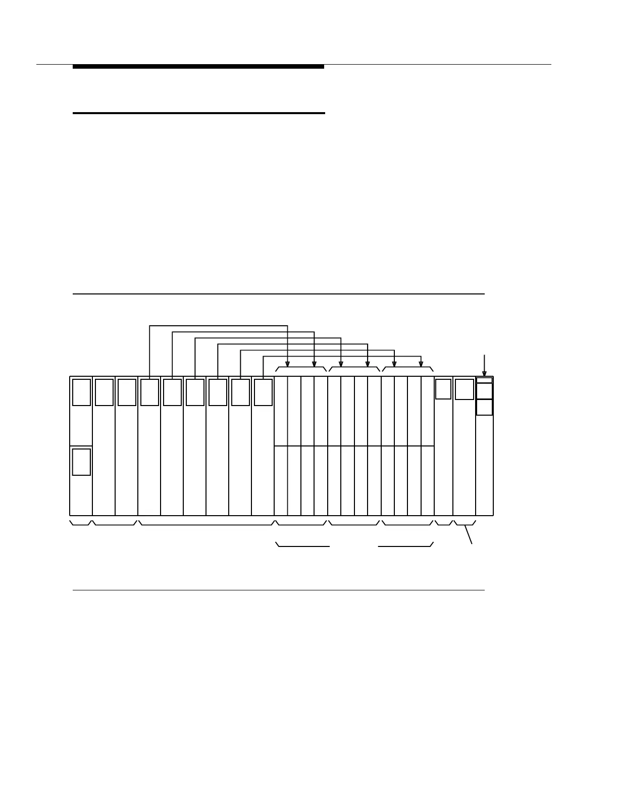
Two independent −48 volt office power feeders (A and B) enter the shelf through
dangler cables and are distributed, after fuses, to the circuit packs. These feeder
fuses are located on the user panel. Power conversion is performed through
modular power converters located on the circuit packs. In each circuit pack, the
two feeders are diode ORed, fused, filtered, and regulated by the board-mounted
power modules. This provides the required redundancy in case of the loss of one
feeder or one fuse. Figure 4-1 shows which circuit packs have converters
mounted on the printed wiring boards. Power modules are located on the TG,
OLIU, MXRVO, OHCTL, SYSCTL, STS1E, and DS3/TMUX circuit packs. The
power converter on the MXRVO/STS1E circuit pack in the Function Unit slots also
provides power to the DS1/DS1PM circuit packs located in the corresponding
multiplexer group.
Figure 4-1. DDM-2000 OC-3 Power Architecture
U
-48V
A
FUSE
-48V
FUSE
B
GROUP A
O
2
O
TGS 1
D
S
1
1
D
S
1
12
56
2(P)
C
FUNCTION UNITS
D
S
D
S
1
2(P)
C
12(P)
ABB
MAIN
L
I
U
1
A
2(P)
TIMING
1
L
I
U
1
TGS
S
S
Y
8(P)
1
D
S
1
1
D
S
1
1
D
S
1
234
67
1
D
S
1
1
5
1
D
S
1
1
58(P)
1
D
S
1
1
D
S
1
1
D
S
1
234
6 7 8(P)
S
C
E
R
P
A
N
E
L
GROUP B AUXCTL
SYSCTL
LOW SPEED
D
S
D
S
D
S
D
S
D
S
D
S
D
S
D
S
GROUP C
T
1
D
S
1
4
1
D
S
1
3
7
D
S
D
S
-48V
A & B
FEEDERS
L
O
H
C
T
L
-48V
+5V
to
-48V
+5V
to
-48V
+5V
to
-48V
+5V
to
-48V
+5V
to
-48V
+5V
to
-48V
+5V
to
-48V
+5V
to
-48V
+5V
to
-48V
+5V
to
+5V
to
-48V
+5V
to
-48V