363-206-285
Circuit Pack Descriptions
7-46 Issue 3 June 2001
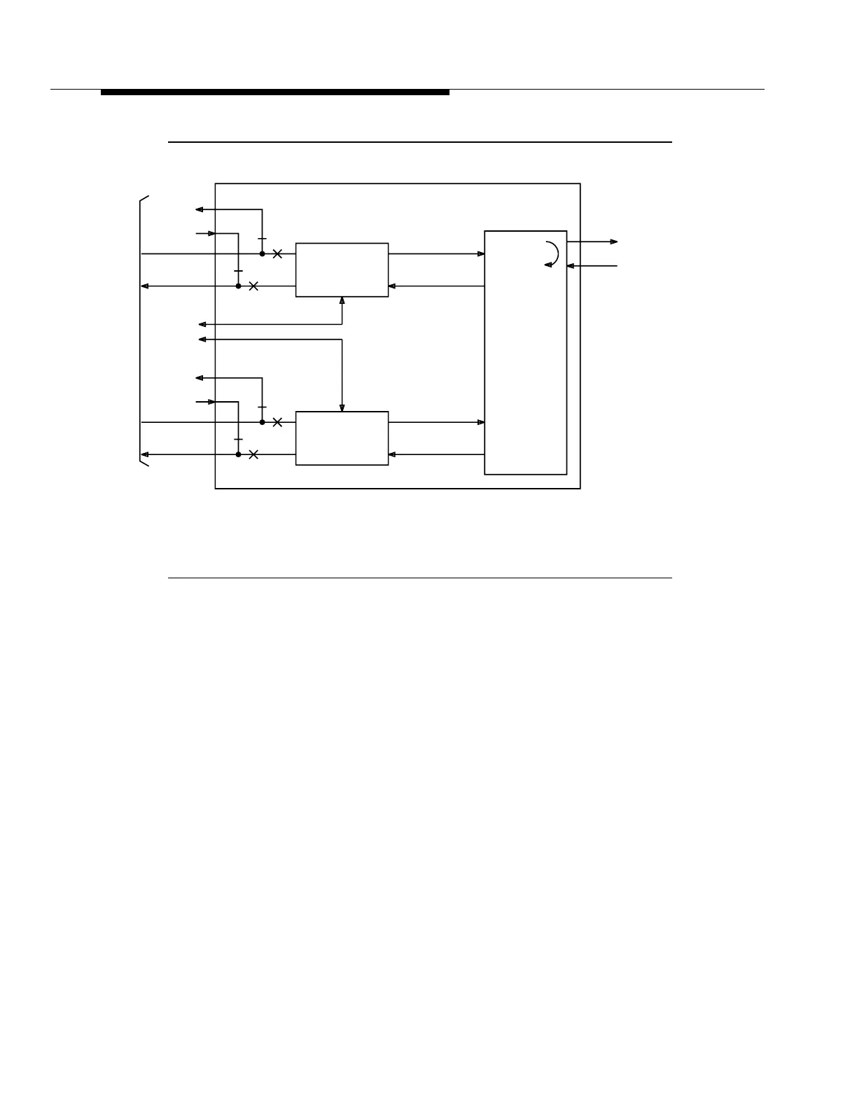
Figure 7-18. HDSL Circuit Pack Block Diagram
The distance limitations for HDSL are based on a maximum signal attenuation of
35 dB. Since signal attenuation decreases as the cable gauge (number)
decreases, the lower the gauge the greater the length the HDSL can be extended.
Table7-2 identifies and lists these distances, as well as indicates the loss on the
line, in dB per feet, at 196 kHz.
Due to the increased power needs of the BBF8, only three BBF8 circuit packs
(including Protection) may be used in a function group. Powering for these packs
is determined by the MXRVO for the OC-3 shelf. The 28-type OLIU is required for
powering in the FiberReach shelf. Pack mixing with Quad DS1 circuit packs is not
allowed. The HDSL interfaces do not support line powering. The BBF8 is
compatible with DDM-2000 Release 6.2 and later.
tpa 852355/01
To / Fr o m
Lightning
Protection
Shelf
To / Fr o m
Prot. Sw.
Bus
HDSL #1
Faceplate
Mounted
Mgt. Port
HDSL to DS1
Processor &
PM Processor
DS1
Clock & Data
VT-G
Loopback
VT 1.5
Processor &
Byte
Interleave &
(Disinterleave)
VT-G
To / Fr o m
MXRVO CPs
(Service and
Protection)
To / Fr o m
Prot. Sw.
Bus
HDSL #2
HDSL to DS1
Processor &
PM Processor
DS1
Clock & Data