363-206-285
Circuit Pack Descriptions
Issue 3 June 2001
7-47
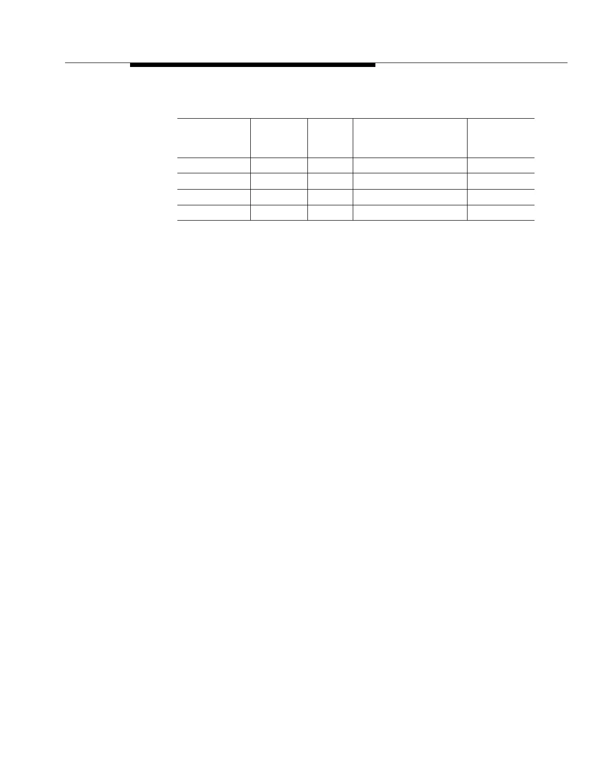
Table 7-1. HDSL Line Specifications
Control Circuitry 7
The HDSL circuit pack interfaces with the SYSCTL over the intra-shelf control
bus. Redundancy in the intra-shelf control bus assures the level of control
required to perform protection switching and alarming of a faulty circuit pack. The
HDLS provides maintenance elements for reporting the status of the circuit pack
and the incoming VT1.5 and HDSL signals, as well as the circuit pack inventory
information (
CLEI
code, date of manufacture, etc.). These maintenance elements
are used by the SYSCTL for fault detection and isolation. Conversely, the HDSL
responds to control signals from the SYSCTL (such as FAULT LED control). The
PM processor collects information from the framing circuitry and generates DS1
PM parameters which are stored in the HDSL pack. Access to the PM information
is via a faceplate-mounted connector. Each connector supports two RS-232
interfaces (one for each HDSL port). The port is accessed by using a cable
supplied with the circuit pack.
Timing Circuitry 7
The timing distribution to the HDSL contains ten timing signals: two high-speed
clocks (active and standby), four VT-G clocks (two active and two standby), and
four frame sync signals (two active and two standby).
The HDSL receives from the MXRVO an STS-1 rate high-speed clock that
provides the frequency reference for the desynchronizing phase-locked loop. This
high-speed reference clock is also used to synthesize the DS1 rate AIS clock
source for the DS1 devices and to provide a DS1 test sigtnal.
The HDSL uses the VT-G clocks (6.912 MHz) and the frame sync signals it
receives from the MXRVO to clock VT-G data to/from the MXRVO.
Protection Circuitry 7
Optional 1xN revertive HDSL circuit pack protection is provided, and this
protection is independent of the MXRVO circuit pack. The HDSL protection switch
points are implemented with on-board relays on the HDSL side and with logic
selectors at the VT-G level on the active and standby MXRVO circuit pack. The
Cable Gauge
Loss at
196 kHz
dB/ft
Ohms
per
kft
Maximum Loop
for 35 dB Loss
Ohms at
Maximum
Length
26/0.40 mm 3.880 83.3 9.0 kft/2.75 km/1.7 mi 750
24/0.51 mm 2.841 51.9 12.3 kft/3.75 km/2.3 mi 638
22/0.61 mm 2.177 32.4 16.1 kft/4.9 km/3.0 mi 520
19/0.91 mm 1.535 16.1 22.8 kft/6.95 km/4.3 mi 367