363-206-285
Transmission and Synchronization Interfaces
5-36 Issue 3 June 2001
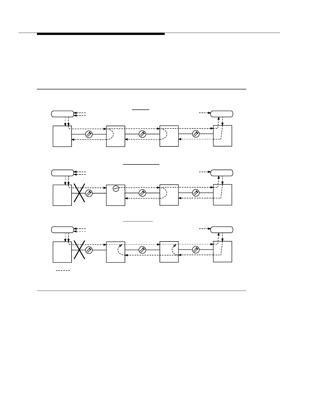
As shown in Figure 5-20 (an OC-3 linear application, although not supported in
Release 13.0, is used to explain the concepts of synchronization messaging), the
use of SONET synchronization messaging notifies the DDM-2000 OC-3
Multiplexer at the slave site to place AIS on the DS1 timing output. This BITS can
then enter holdover or switch to an alternate reference.
Figure 5-20. DS1 Timing Output — Dual Homing Linear
BITS
DDM-2000
DS1
CO
PRS
Traceable
DDM-2000
loop-timed
RT
DDM-2000
loop-timed
DDM-2000
OC-N OC-N OC-N
Normal
BITS
CO
DS1
Failure/Recovery
RT
BITS
DDM-2000
DS1
CO
PRS
Traceable
DDM-2000
RT
DDM-2000
loop-timed
DDM-2000
OC-N OC-N OC-N
BITS
CO
DS1
RT
holdover
AIS
PRS
Traceable
PRS
Traceable
BITS
DDM-2000
DS1
CO
PRS
Traceable
DDM-2000
RT
DDM-2000
loop-timed
DDM-2000
OC-N OC-N OC-N
BITS
CO
DS1
RT
AIS
PRS
Traceable
Reconfigured
loop-timed
a.)
b.)
c.)
Sync Flow
Ext
Timed
Ext
Timed
Ext
Timed
Ext
Timed
Ext
Timed
Ext
Timed