363-206-285
Circuit Pack Descriptions
Issue 3 June 2001
7-113
Detailed Description of Operation 7
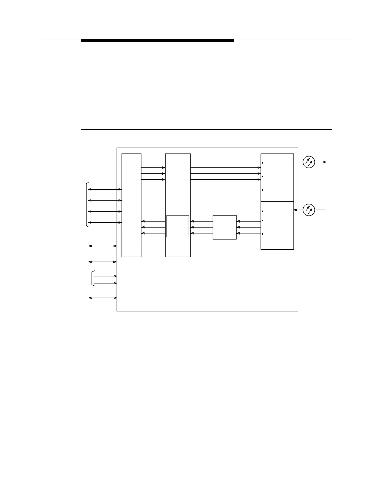
Figure 7-42 is a block diagram of the 22D-U OLIU circuit pack.
The STS-1 router is used to select STS-1s for both the transmit and receive
directions. All incoming STS-1s are fed to the VT1.5 cross-connect. Outgoing
STS-1s may be sourced by this VT1.5 cross-connect or sourced directly by an
STS-1 input.
Figure 7-42. 22D-U OLIU Circuit Pack Block Diagram
Transmit Direction. 7The STS-1 router selects three of the STS-1 signals directly
from the other main and function unit slots or from the VT1.5 cross-connect.
SONET path overhead is then added to STS-1s sourced by the VT1.5 cross-
connect before the signals are sent to the multiplexer. The multiplexer takes the
three STS-1 signals, adds SONET transport overhead, then byte-interleaves and
scrambles the signal with a frame synchronous scrambler. The output from the
multiplexer is in the SONET STS-3 format and is used to amplitude modulate the
STS-1 #1
STS-1 #2
STS-1 #1
STS-1 #2
STS-1 #3
Pointer
STS-1 #3
STS-1
Processor
STS-1 #1
STS-1 #2
STS-1 #3
STS-1 #1
STS-1 #2
STS-1 #3
STS-1 #1
STS-1 #2
Multiplexer
3 STS-1s into
Write Section
and Line OH
Bytes of STS-1 #1
Converts STS-3
into OC-3
Demultiplexer
Converts OC-3
to STS-3
Section and Line
OH
Processes
VT1.5
and/or
STS-1 #3
Byte
STS-3 into
3 STS-1s
Intrashelf
STS-1
Te r m i n-
ation
VT1.5
Pointer
Processor
Cross
Connect
-48V B
Timing
STS-1
Router
Path
Overhead
an STS-3
Byte Interleaves
Disinterleaves an
Overhead
Transport
Control
Protection)
(Service &
SONET
From
Fuses
To / Fr o m
Slots
To / Fr o m
SYSCTL
To / Fr o m
OHCTL
Main/FN
-48V A
-48V Shelf
OC-3
OC-3
(Service &
Protection)
To / Fr o m
TGS CPs
Tx Fiber
(Service or
Protection)
Rx Fiber
(Service or
Protection)
STS-1 #1
STS-1 #2
STS-1 #3
STS-1 Ring