363-206-285
Transmission and Synchronization Interfaces
5-48 Issue 3 June 2001
Synchronization Messaging to Support DS1 Timing Outputs 5
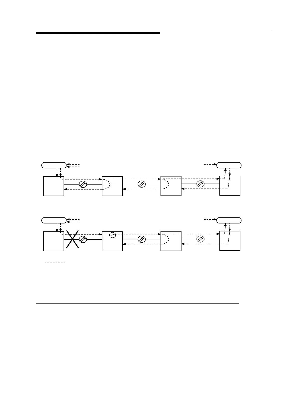
Figure 5-24a (an OC-3 linear application, although not supported in Release 13.0,
is used to explain the concepts of synchronization messaging) shows a dual
homing linear network operating in its normal configuration. The DDM-2000 OC-3
Multiplexer at site A is externally timed, and the DDM-2000 OC-3 Multiplexers at
sites B and C are line-timed from site A. The DDM-2000 OC-3 Multiplexer at site
D is also externally timed from another BITS. Both BITS should be PRS traceable.
The SQU message is sent to indicate where timing is traceable to an external
BITS and where it is valid to be used. The TLB message is sent to indicate where
line timing has been used and, thus, where using that timing would create a timing
loop. Synchronization messaging has been enabled for this network, but
automatic synchronization reconfiguration has not been enabled.
Figure 5-24. DS1 Timing Output with Fiber Failure (Sheet 1 of 2 )
BITS
Sync Flow
DDM-2000
DS1
CO
PRS
Traceable
DDM-2000
RT
DDM-2000
DDM-2000
BITS
CO
DS1
RT
BITS
DDM-2000
DS1
CO
PRS
Traceable
DDM-2000
RT
DDM-2000
DDM-2000
SQU SQU
BITS
CO
DS1
RT
DS1
a) Before Failure
b) After Failure, Site B Changes Message
Site A Site B Site C Site D
PRS
Traceable
PRS
Traceable
Site A Site B Site C Site D
TLB TLB
TLBTLB TLB
SQU SQU SQU
DS1
STRATUM 3 if using a TG3 at site B, or IC if using a TG3.
IC
*
*