363-206-285
Transmission and Synchronization Interfaces
Issue 3 June 2001
5-47
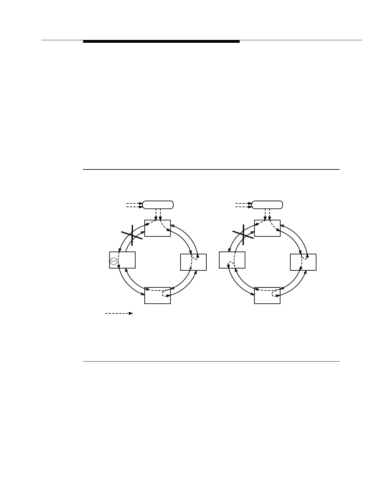
In Figure 5-23e, the DDM-2000 OC-3 Multiplexer at site C detects the incoming
SQU message from site D. The SQU message is a better quality message than
the IC message being received from site B, so the DDM-2000 OC-3 Multiplexer at
site C switches to line time from site D. After the switch occurs, the TLB message
is sent back to site D, and the SQU message is retransmitted to site B.
In Figure 5-23f, the DDM-2000 OC-3 Multiplexer at site B detects the incoming
SQU message from site C. The SQU message is a better quality message than
the internal holdover capability, so the DDM-2000 OC-3 Multiplexer at site B
switchestolinetimefromsiteC.Aftertheswitchoccurs,theTLBmessageissent
backtositeC,andtheSQUmessageisforwardedtositeA.Whenthefailure
clears, the synchronization remains in the new configuration unless it is manually
switched back.
Figure 5-23. Synchronization Reconfiguration — Access Ring (Sheet 3 of 3 )
PRS
Traceable
BITS
DDM-2000
DDM-2000
DDM-2000
PRS
Traceable
BITS
Sync Flow
SQU
Site A
Site D
Site B
Site C
SQU
TLB
TLB
SQU
DDM-2000
DDM-2000
SQU
Site A
Site D
Site B
Site C
SQU
TLB
SQU
f) Site B Reconfigures
IC
TLB
e) Site C Reconfigures
SQU
TLB
SQU
SQU
DDM-2000
DDM-2000
DDM-2000
IC
STRATUM 3 if using a TG3 at site B, or IC if using a TGS.
*
*