363-206-285
Circuit Pack Descriptions
Issue 3 June 2001
7-97
BBG20 TMUX Hardware Settings 7
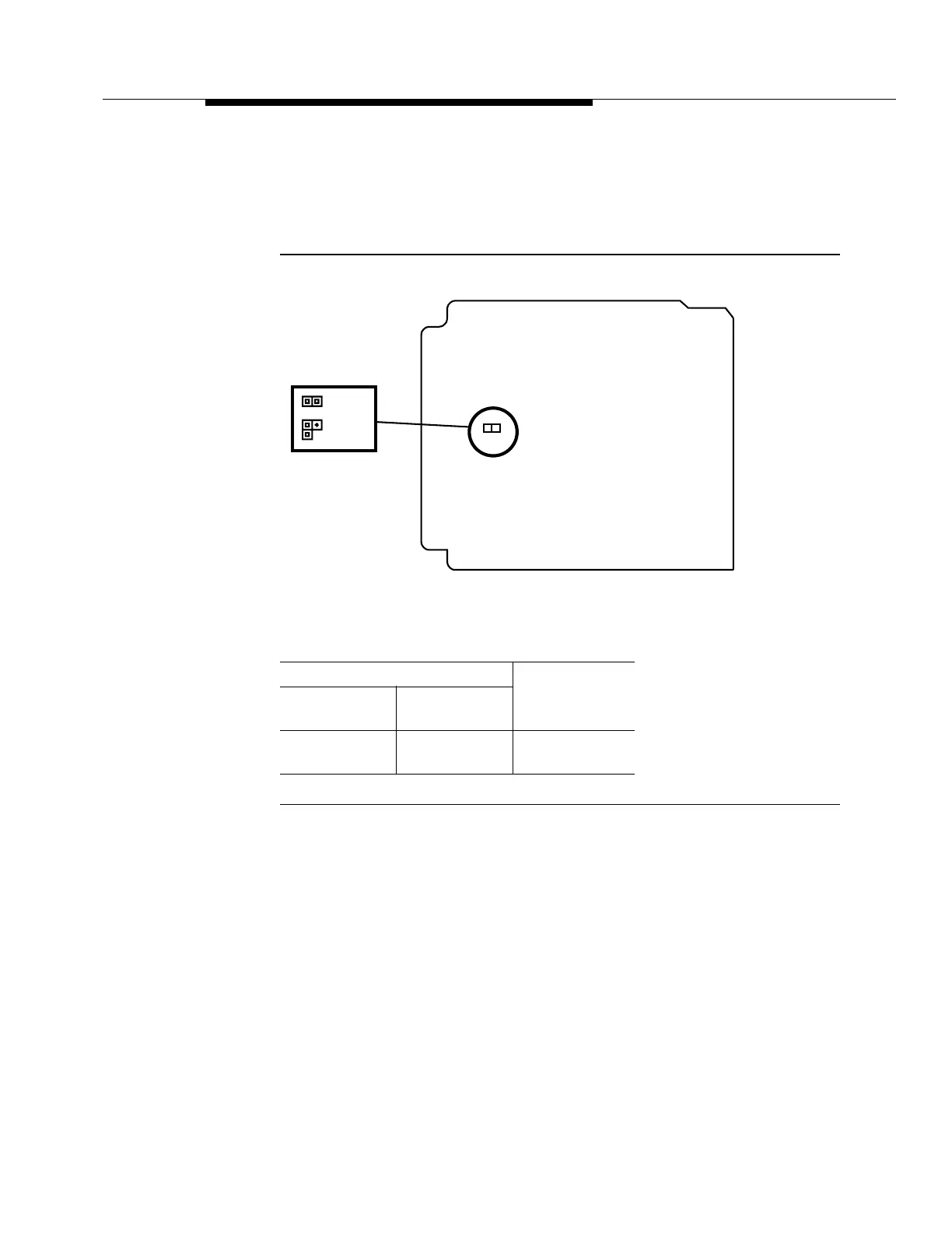
The location of the TMUX circuit pack LBO jumpers is shown in Figure 7-37. The
TMUX DS3 LBO settings are shown in the table.
BBG20 TMUX LBO Settings
Figure 7-37. BBG20 TMUX Line Build-Out (LBO) Jumpers
Power Circuitry 7
The BBG20 TMUX circuit pack receives two sources of -48 volts that are in turn
diode ORed, fused, and filtered before conversion to +5 volts to power the rest of
the circuit pack. A failure of the fuse or converter causes the red FAULT LED to
light.
Cable Length (Ft)
735A
Cable
734D
Cable
LBO Setting
0to65
>65to250
0to120
>120 to 450
LBO ON
LBO OFF
Edge
Connector
Component Side
P3
= ON
= OFF