363-206-285
Transmission and Synchronization Interfaces
Issue 3 June 2001
5-9
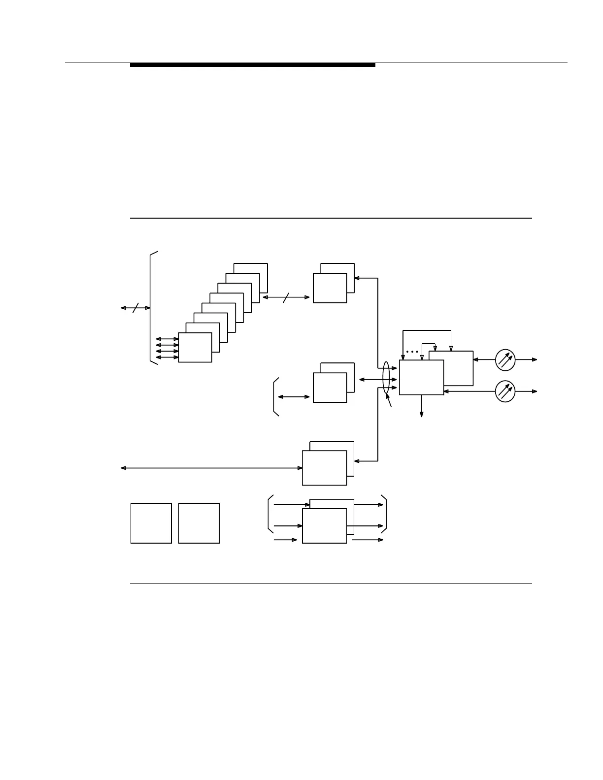
Figure 5-5 is an overall block diagram of the DDM-2000 OC-3 Multiplexer in a
terminal configuration. In this case, however, 29 type OLIUs are installed in main
providing OC-12 optics in an OC-3 shelf.
The 29 type OLIU receives an OC-12 signal and converts it to an electrical
STS-12. This STS-12 is then demultiplexed into 12 STS-1 signals with the
capability of routing any of these 12 STS-1s to the function unit slots. The STS-1s
that are dropped can contain any combination of VT-G, EC-1, or DS3 signals
routed to the function units.
Figure 5-5. DDM-2000 OC-3 Multiplexer with OC-12 Optics Block Diagram
Low Speed
8(P)
7
6
5
4
3
2
1
DS1
VT-G
DS1
28
Function
Unit
2(P)
1
STS-1
7
MXRVO
DS1
2(P)
1
STS1E
STS-1
STS-1
1
Receive
Clocks to
the TGSs
1
2(P)
Main
External
Reference
Inputs
Receive
Clocks from
the Main
OLIUs
1
2(P)
DS1
DS1
DS1
DS1
Reference
Outputs
Intrashelf
Timing to Main
and Function
Unit Slots
Timing
Control
SYSCTL
OHCTL
TGS
DS3
DS3
EC-1
(Note 2)
OLIU
(Note 1)
2
OC-12
OC-12
(Note 3)
12 STS-1s
Notes:
1. 29-type OLIU only.
2. Any of the 12 STS-1s can
be dropped at this node.
3.Through-connection for up to
12 STS-1s via a 29G-U OLIU
faceplate connector.