363-206-285
Circuit Pack Descriptions
7-18 Issue 3 June 2001
Detailed Description of Operation 7
Control Circuitry 7
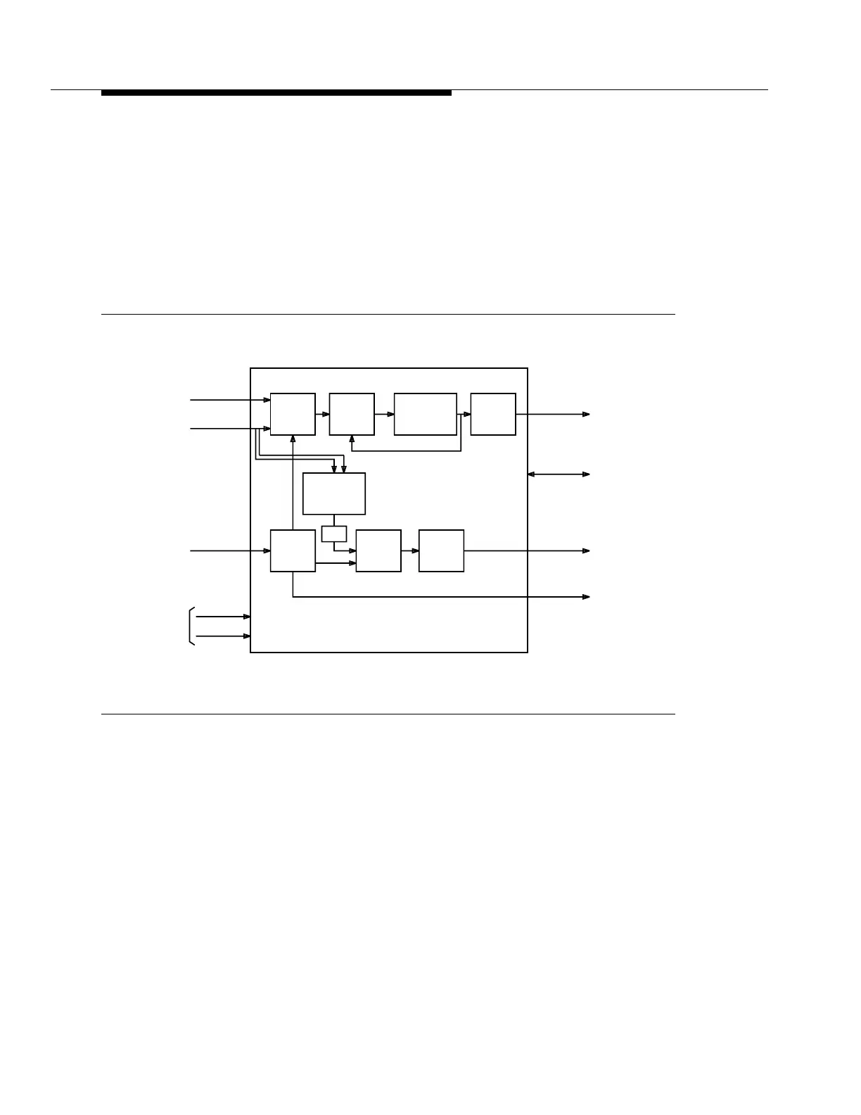
Figure 7-7 is an overall block diagrams of the BBF2B TGS and BBF4 TG3 circuit
packs. The TG circuit pack interfaces with the SYSCTL via the intra-shelf control
bus. Through this interface, the SYSCTL monitors the health of the TG circuit
pack to provide alarm reporting. The SYSCTL also controls TG circuit pack
switching and mode functions, as well as controlling the faceplate LEDs.
Figure 7-7. BBF2B TGS and BBF4 TG3 Circuit Pack Block Diagram
PLL
Digital
Internal
Oscillator
Output
Drivers
Outputs
Timing
-48V A
-48V B
From
Fuses
Timing
Select
From
Companion
TGS
Cross-coupled
Reference
Mode
Line Timing
References
DS1 Output
Source
Select
DS1
Interface
DS1
Output
Mode
Xmit
DS1
Interface
PLL
To / Fr o m
SYSCTL
To Next
Shelf or BITS
Clock
To
Companion
TGS
Cross-coupled
Reference
Intrashelf
Control
DS1
Output
To Main
and
Function
Unit Slots
(Service and
Protection)
-48V Shelf
DS1
Reference
From
Stratum 3
Clock
From Main
OLIUs
and for OC-3
only, Function
Unit C Slot
(Service and
Protection)