363-206-285
Transmission and Synchronization Interfaces
Issue 3 June 2001
5-49
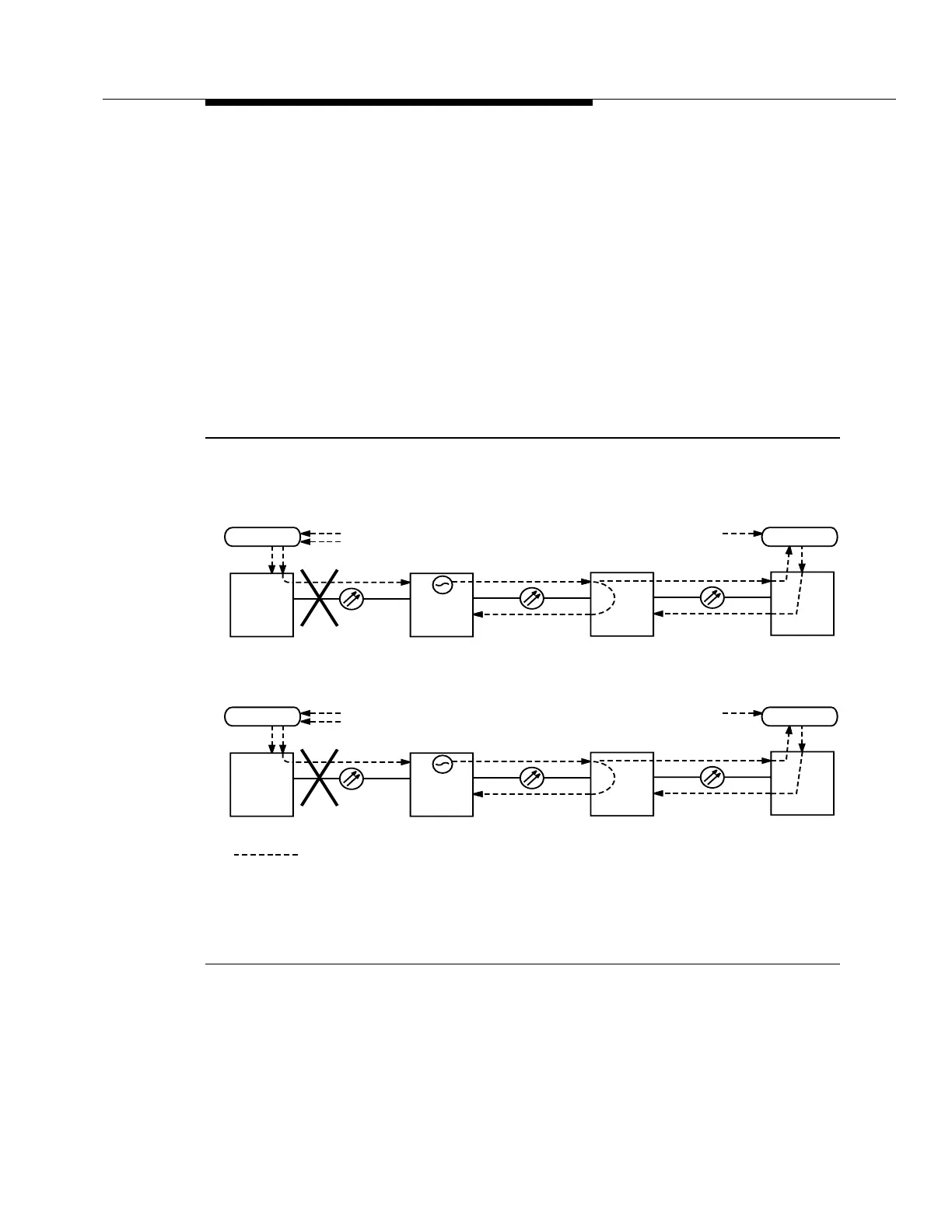
In Figure 5-24b, a fiber has been cut between sites A and B. Immediately, the
DDM-2000 OC-3 Multiplexer at site B enters holdover and sends out the IC
messagetositeC.
In Figure 5-24c, the DDM-2000 OC-3 Multiplexer at site C detects the incoming IC
message from site B and forwards it on to site D.
In Figure 5-24d, the DDM-2000 OC-3 Multiplexer at site D detects the incoming IC
message from site C and sends out AIS to the BITS. The BITS will either switch to
an alternate reference, if available, or enter holdover.
If the automatic synchronization reconfiguration feature had been enabled in this
example, at this point, sites C and B would attempt to switch line timing directions
to retime from site D.
Figure 5-24. DS1 Timing Output with Fiber Failure (Sheet 2 of 2)
BITS
Sync Flow
DDM-2000
DS1
CO
PRS
Traceable
DDM-2000
RT
DDM-2000
DDM-2000
BITS
CO
DS1
RT
BITS
DDM-2000
DS1
CO
PRS
Traceable
DDM-2000
RT
DDM-2000
DDM-2000
SQU
BITS
CO
DS1
RT
DS1
Site A Site B Site C Site D
PRS
Traceable
PRS
Traceable
Site A Site B Site C Site D
TLB SQU
TLB TLB
SQU
c) Site C Changes Message
d) Site D Changes Message
AIS
DS1
IC
IC
IC IC
STRATUM 3 if using a TG3 at site B, or IC if using a TGS.
*
**
*
*