363-206-285
Power
4-6 Issue 3 June 2001
Power Distribution 4
See "Power Requirements" in Section 10, "Technical Specifications," for power
dissipation values.
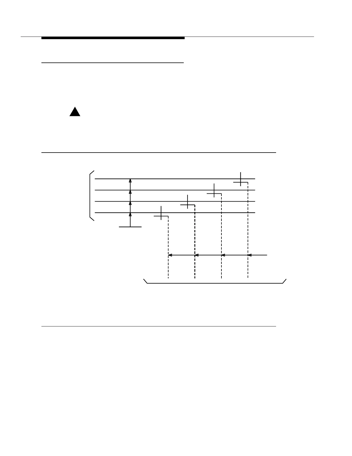
Figure 4-3 shows a typical battery feeder interface for a single shelf.
!
CAUTION:
This information is for a typical application only. Consult
801-525-168
, DDM-2000
Floor Plan Data Sheets, and T-82046-30, Power Systems DC Distribution Circuit for
Digital Transmission System, for proper engineering of battery plant and feeders.
Figure 4-3. Typical −48 Volt Power Supply for DDM-2000 OC-3 Multiplexer Single Shelf
RTN (A)
RTN (B)
-48 V (A)
-48 V (B)
-48 V (A)RTN (A)RTN (B) -48 V (B)
12 GA
To DDM-2000 Shelf
NOTE
NOTE: Feeder size is selected per T82046-30 and EIM 90MV001, Issue 5.
To Fuse
Protection
At -48 V Battery
Distribution
Fuse Board