DLP-501: Detailed Level Procedure 363-206-285
Page 2 of 8 Issue 2, February 2000
DDM-2000 OC-3 MULTIPLEXER
4.
!
CAUTION:
Removing the
BBG5 SYSCTL
without performing a 10-second
countdown sequence on the
FE ID
display may result in unexpected and
undesirable protection switches, incorrect circuit pack fault indications, or
incoming signal failure indications.
Momentarily depress the ACO/TST pushbutton on the User Panel and the FE
SEL pushbutton on the SYSCTL atthesametimetostarta10-second
countdown (9, 8, 7, etc.) on the FE ID display. During this countdown, remove
the SYSCTL.IftheSYSCTL is failed, the countdown may not occur.
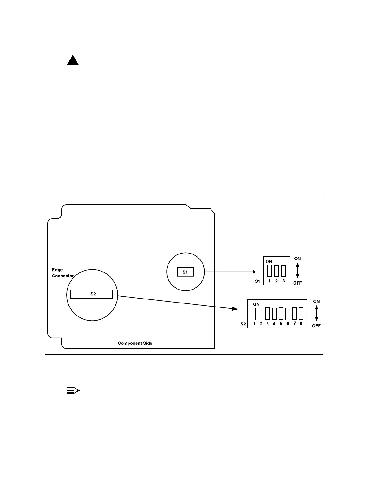
5. Set all SYSCTL switch S1 sections S1-1, S1-2, and S1-3 to OFF,tosetthe
product (shelf) type. See Figure 1.
6. Set all SYSCTL switch S2 sections S2-1, S2-2, S2-3, S2-4, S2-5, S2-6, S2-7,
and S2-8 to OFF.
Figure 1 – BBG8/BBG8B SYSCTL Option Settings
7.
NOTE:
Steps 8 and 9 must be performed without unnecessary delays.
Familiarize yourself with these steps before continuing with the
procedure.
Read Steps 8 and 9 before proceeding.