363-206-285 Detailed Level Procedure: DLP-502
Issue 2, February 2000 Page 2 of 2
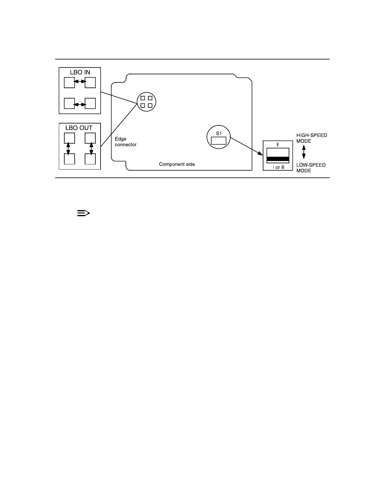
DDM-2000 OC-3 MULTIPLEXER
Figure 1 – BBG6 STS1E Option Settings
5.
NOTE:
If the response is not correct in the following procedures, replace the
BBG6 STS1E circuit pack.
Seat a BBG6 STS1E circuit pack in FUNCTION UNITS group slot A-1, B-1,or
C-1.
Response: FAULT LED on the STS1E lights for about 20 seconds
then goes off. ACTIVE LED lights on the first BBG6
STS1E circuit pack of the pair installed.
6. If required, seat a second (protection) BBG6 STS1E circuit pack in
FUNCTION UNITS group slot A-2(P), B-2(P),orC-2(P) of the same
FUNCTION UNITS group.
Response: FAULT LED on the STS1E lights for about 20 seconds
then goes off. ACTIVE LED remains off.
7. Repeat this procedure from Step 1 for each pair of BBG6 STS1E circuit packs
to be installed.
8. STOP. YOU HAVE COMPLETED THIS PROCEDURE.