363-206-285 Detailed Level Procedure: DLP-503
Issue 2, February 2000 Page 6 of 10
DDM-2000 OC-3 MULTIPLEXER
NOTE:
If an invalid switch setting is selected, the TGS/TG3 FAULT LED lights
and an alarm is generated.
Refer to Table C and Figure 1 (BBF2 TGS) or Table D and Figure 2
(BBF2B/BBF2C TGS or BBF4 TG3). Set the timing mode as required for the
TGS circuit pack being installed.
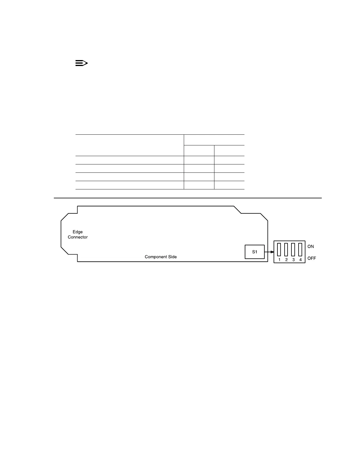
Figure 1 – BBF2 TGS Option Switch
Table C – BBF2 TGS Timing Mode Switch Setting
Timing Mode
Switch S1 Settings
S1-3 S1-4
Free Running ON ON
DS1 External, MULT Mode OFF ON
Line Timed ON OFF
Invalid OFF OFF