363-206-285 Detailed Level Procedure: DLP-503
Issue 2, February 2000 Page 8 of 10
DDM-2000 OC-3 MULTIPLEXER
2. If the BBF2B/BBF2C TGS or BBF4 TG3 circuit pack is being installed and is
provisioned for either
sync out
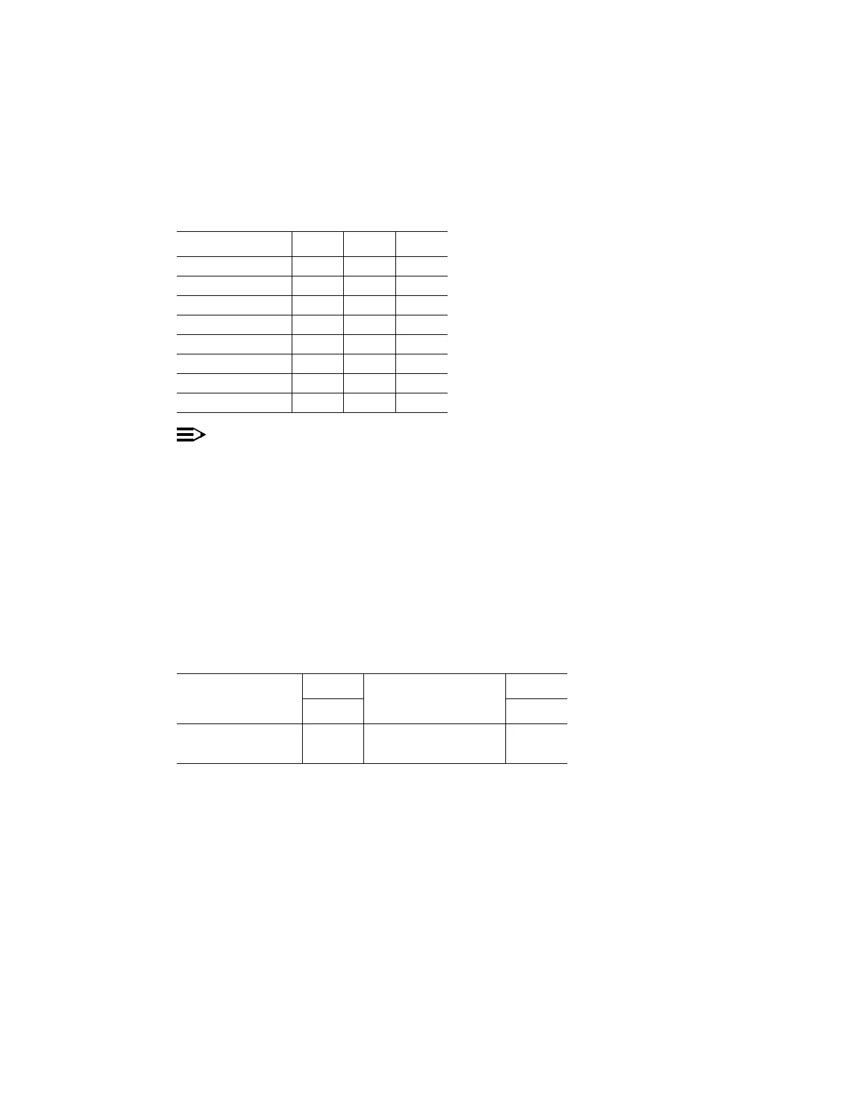
mode, refer to Table E and set the equalizer
switches for proper cable length.
3.
NOTE:
Switches S1-1 and S1-2 are ignored by the system unless the timing
mode is set to
DS1 External
or
Line Timed sync out mode
.
Is timing mode set to either
DS1 External
or
Line Timed sync out mode
?
If YES, then continue with Step 4.
If NO, then proceed to Step 5.
4. Refer to Table F and set the DS1 line coding and frame format as required for
the TGS/TG3 circuit pack. See Figures 1 and 2.
Table E – Equalizer Switch Settings
Equalization S2-1 S2-2 S2-3
0’ to 131’ ON ON OFF
>131’ to 262’ ON OFF ON
>262’ to 393’ ON OFF OFF
>393’ to 524’ OFF ON ON
>524’ to 655’ OFF ON OFF
Invalid OFF OFF OFF
Invalid OFF OFF ON
Invalid ON ON ON
Table F – TGS/TG3 DS1 Line Coding and Frame Format Switch Settings
DS1 Line Code
Switch
DS1 Frame Format
Switch
S1-1 S1-2
AMI ON SF ON
B8ZS OFF ESF OFF