DLP-508: Detailed Level Procedure 363-206-285
Page 2 of 4 Issue 2, February 2000
DDM-2000 OC-3 MULTIPLEXER
3.
NOTE:
DS1 line coding may be set using either the option switches OR the
set-t1 command. It is recommended that a policy be established to set
line coding using either the switches OR the command. If DS1 line code
(lc) parameters are set using the set-t1 command, a software override
will be active and the circuit pack switch settings will have no effect. The
software override will remain active until the set-t1 command is
executed again and the noOverride option is selected. The rtrv-t1
command may be used to check line code settings.
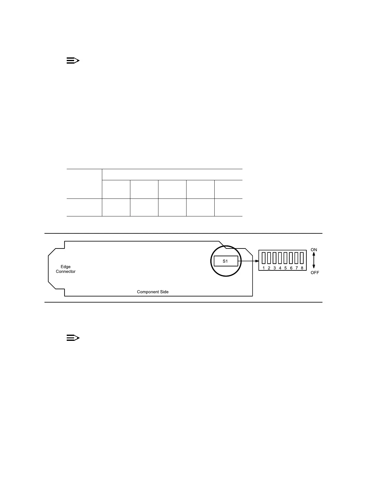
Refer to Table B and Figure 1 and set the line code option switches, if required.
Note: Switch 1, section 8 (S1-8) is unused and ignored by the system.
Figure 1 – DS1/DS1PM Option Settings
4.
NOTE:
If the response is not correct when the DS1/DS1PM circuit pack is
installed, check option switch setting. If settings are correct, replace the
DS1/DS1PM circuit pack.
Seat DS1/DS1PM circuit pack in required slot of LOW SPEED group being
equipped.
Response: FAULT LED on DS1/DS1PM circuit pack lights and may
remain lighted for about 40 seconds and then goes off.
Table B – DS1/DS1PM Line Code Settings
Line Code
Format
Switch S1 Settings
S1-4
(Port 1)
S1-5
(Port 2)
S1-6
(Port 3)
S1-7
(Port 4)
S1-8
(Note)
B8ZS OFF OFF OFF OFF
OFF
AMI ON ON ON ON