DLP-513: Detailed Level Procedure 363-206-285
Page 10 of 20 Issue 2, February 2000
DDM-2000 OC-3 MULTIPLEXER
NOTE:
To set switch to ON, depress rocker or slide switch toward side labeled
ON in figure. To set switch to OFF, depress rocker or slide switch toward
side labeled OFF in figure.
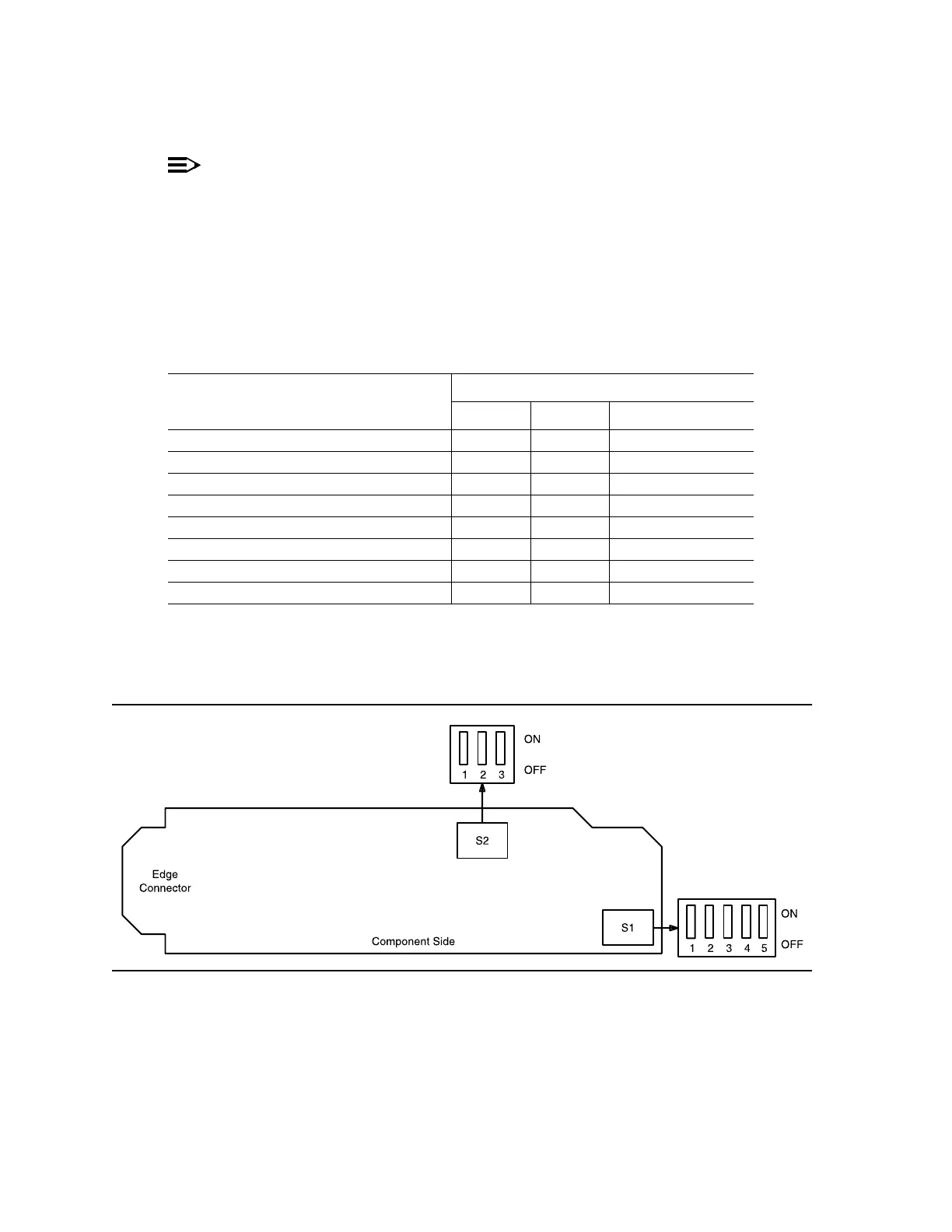
Determine timing mode from work order or office records. Refer to Table F and
Figure 3 and set timing mode as required for BBF2B/BBF2C TGS or BBF4
TG3 circuit pack(s).
Figure 3 – BBF2B/BBF2C TGS or BBF4 TG3 Option Switch
Table F – BBF2B/BBF2C TGS/BBF4 TG3 Timing Mode Switch Settings
Timing Mode
Switch S1 Settings
S1-3 S1-4 S1-5 (DS1 Output)
Free Running* ON ON OFF
DS1 External, MULT Mode OFF ON OFF
Line Timing, MAIN† ON OFF OFF
Line Timing, SYNC OUT Mode† ON OFF ON
DS1 External, SYNC OUT Mode† ON ON ON
Invalid‡ OFF OFF ON
Invalid‡ OFF OFF OFF
Invalid‡ OFF ON ON
* Factory default.
†MainOLIU is default; FUNCTION UNIT C by set-sync command.
‡ If an invalid setting is selected, FAULT LED is lighted and an alarm is
generated (unexpected CP type or unexpected CP switches).