363-206-285 Detailed Level Procedure: DLP-535
Issue 2, February 2000 Page 2 of 4
DDM-2000 OC-3 MULTIPLEXER
NOTE:
If the BBF2B/BBF2C TGS or BBF4 TG3 timing mode is set to DS1
External sync out mode, an ED-8C724-20, G394 cable must be
connected to jack J37 on the shelf backplane (or J237 of the front access
cable). This cable has a relay to disconnect the incoming external timing
supply if the TGS/TG3 circuit pack is removed.
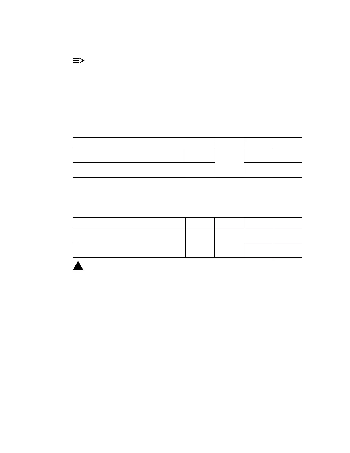
Make DS1 external timing reference connections as shown in Table A.
6. Make synchronization DS1 timing output connections as shown in Table B, if
required.
7.
!
CAUTION:
A momentary transmission hit (error) will occur when the
TGS
circuit
pack is switched.
Is a CIT available?
If YES, then continue with Step 8.
If NO, then proceed to Step 9.
8. Use switch-sync:s=circuitpack,pri=manual command to switch
timing to protection TGS in TIMING slot 2, if not already active.
Response: ACTIVE LED lights on TGS circuit pack in TIMING slot 2.
Table A – DS1 External Timing Reference Source Connections
Name Desig. Conn. Term. Color
Receive from Primary DS1 Reference
T
R
P37
6
1
BK
O
Receive from Secondary DS1 Reference
T
R
7
2
R
G
Table B – DS1 Timing Output Connections
Name Desig. Conn. Term. Color
Transmit Primary DS1 Reference
T
R
P44
6
1
BK
O
Transmit Secondary DS1 Reference
T
R
7
2
R
G