363-206-285
Transmission and Synchronization Interfaces
5-44 Issue 3 June 2001
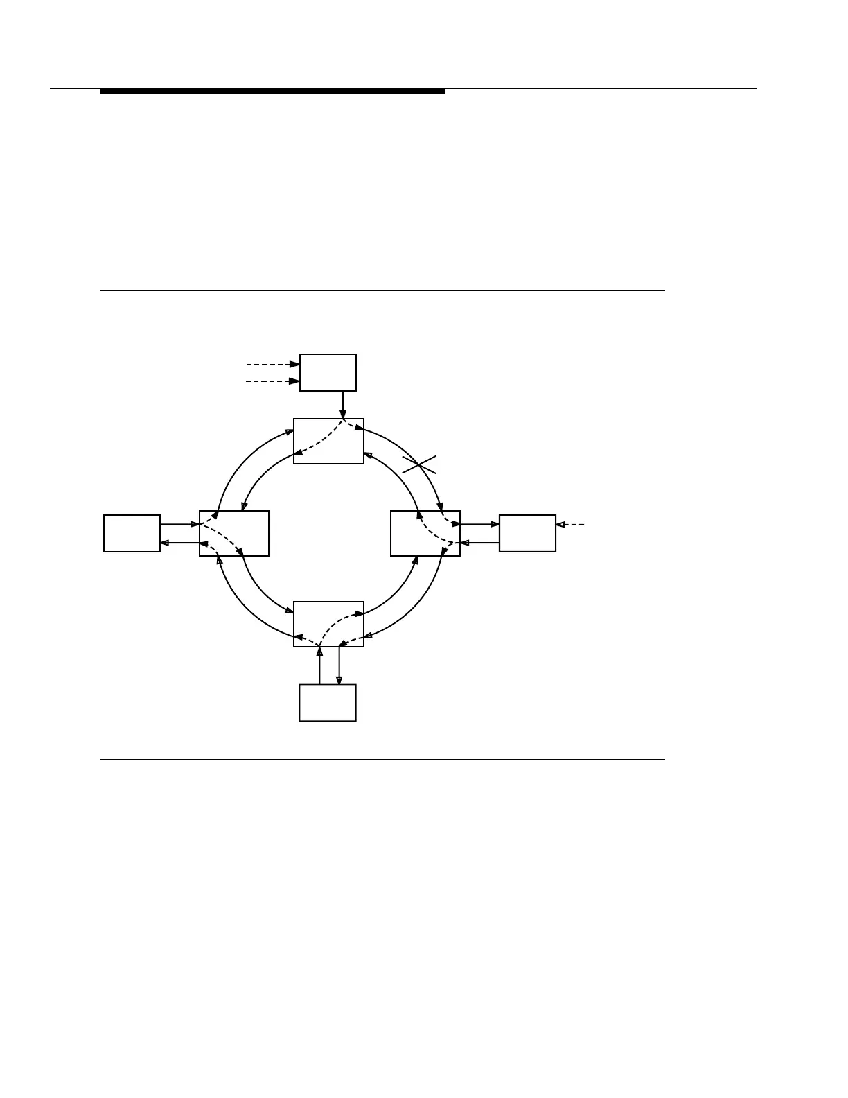
In Figure 5-22b, a fiber has been cut between sites A and B. Immediately the
DDM-2000 OC-3/OC-12 Multiplexer at site B changes the format of its derived
DS1 to AIS. This forces the BITS clock at site B to enter holdover or switch input
source (if a valid one is available). Because automatic synchronization
reconfiguration is not available, the synchronization status messages are not
used. All other non-host nodes will track the holdover clock at site B. Although no
timing loops have been formed, the timing of all non-host nodes will differ from the
host node by the accuracy of the holdover clock at site B.
Figure 5-22. Synchronization Reconfiguration — Externally Timed Access Ring
(Sheet 2 of 2)
SQU
SQU
SQU
DDM-2000
Site A
DDM-2000
Site B
DDM-2000
Site D
DDM-2000
Site C
BITS
CLOCK
BITS
CLOCK
BITS
CLOCK
SQU
SQU SQU
SQU
BITS
CLOCK
b) Synchronization Reconfiguration (After Failure)
AIS
Holdover
Mode
PRS Traceable
Source
Alternate PRS
Traceable Source