363-206-285 Detailed Level Procedure: DLP-560
Issue 2, February 2000 Page 15 of 18
DDM-2000 OC-3 MULTIPLEXER
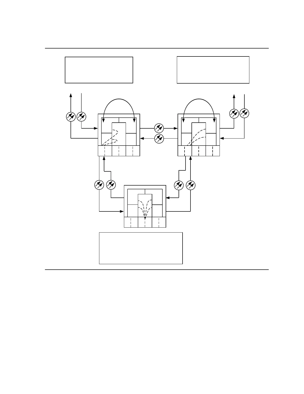
Figure 11 – Example of Dual Homing OC-12/OC-3 Cross-Connections (OC-3
with OC-12 Optics)
m-1 to a-1
(ent-crs-sts1:m-1,a-1)
where:
m-1 = address of STS #1 in MAIN OLIU
a-1 = address of STS #1 in LOW
SPEED GROUP A OLIU
m-1 to a-1
(ent-crs-sts1:m-1,a-1)
where:
m-1 = address of STS #1 in MAIN OLIU
a-1 = address of STS #1 in LOW SPEED
GROUP A OLIU
b-2-1 to m-1-2-1
(ent-crs-vt1:b-2-1,m-1-2-1)
where:
b-2-1 = address of DS1 port 1, circuit pack #2,
in LOW SPEED GROUP B
m-1-2-1 = address of VT#1, VTG #2, STS #1
in MAIN OLIUs.
IN
OUT
IN
OUT
OC-12
OC-12
IN
OUT
MAIN 1
MAIN 1 MAIN 1
MAIN 2
MAIN 2 MAIN 2
Node 1
A
AA
B
BB
C
CC
C
CC
B
BB
1
11
1
11
2(P)
2(P) 2(P)
2(P)
2(P) 2(P)
A
AA
1
11
DDM-2000 OC-3
NS
US
NS
NS NS
US
US
US
OC-3
OC-3
2(P)
2(P) 2(P)
TSI
TSI TSI
OC-12
OC-12 Path Switched Ring with
OC-3 Shelves with OC-12 Optics
Node 5
DDM-2000
OC-12
Node 4
DDM-2000
OC-12
Faceplate Connector
Passes Through
Undropped STSs