363-206-285
Circuit Pack Descriptions
Issue 3 June 2001
7-81
STS1E Hardware Settings 7
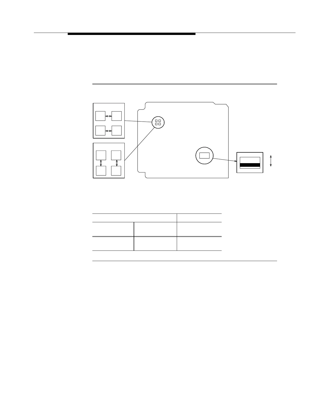
The location of the STS1E circuit pack LBO jumpers and mode switch are shown
in Figure 7-31. The STS1E LBO settings are shown in the table.
STS1E LBO Settings
Figure 7-31. BBG6 STS1E Line Build-Out (LBO) Jumpers and Mode Switch
STS1E Quick Reference Summary 7
Transmit Functions (High-Speed Mode) 7
The STS1E transmit (high-speed mode) functions are as follows:
■ Selects VT-Gs from DS1/DS1PM circuit packs, multiplexes VT-Gs with
protection selection into a SPE, and adds STS-1 path overhead
■ Adds SONET transport overhead, B3ZS encodes and scrambles data,
converts to bipolar format, and sends it to the STSX-1.
Cable Length (Ft) LBO Setting
735A
Cable
734D
Cable
0 to 125
>125 to 250
0 to 225
>225 to 450
LBO IN
LBO OUT
LBO IN
Edge
Connector
LBO OUT
Component Side
II
I or III
HIGH-SPEED
MODE
LOW-SPEED
MODE
S1