363-206-285
Maintenance Description
Issue 3 June 2001
9-29
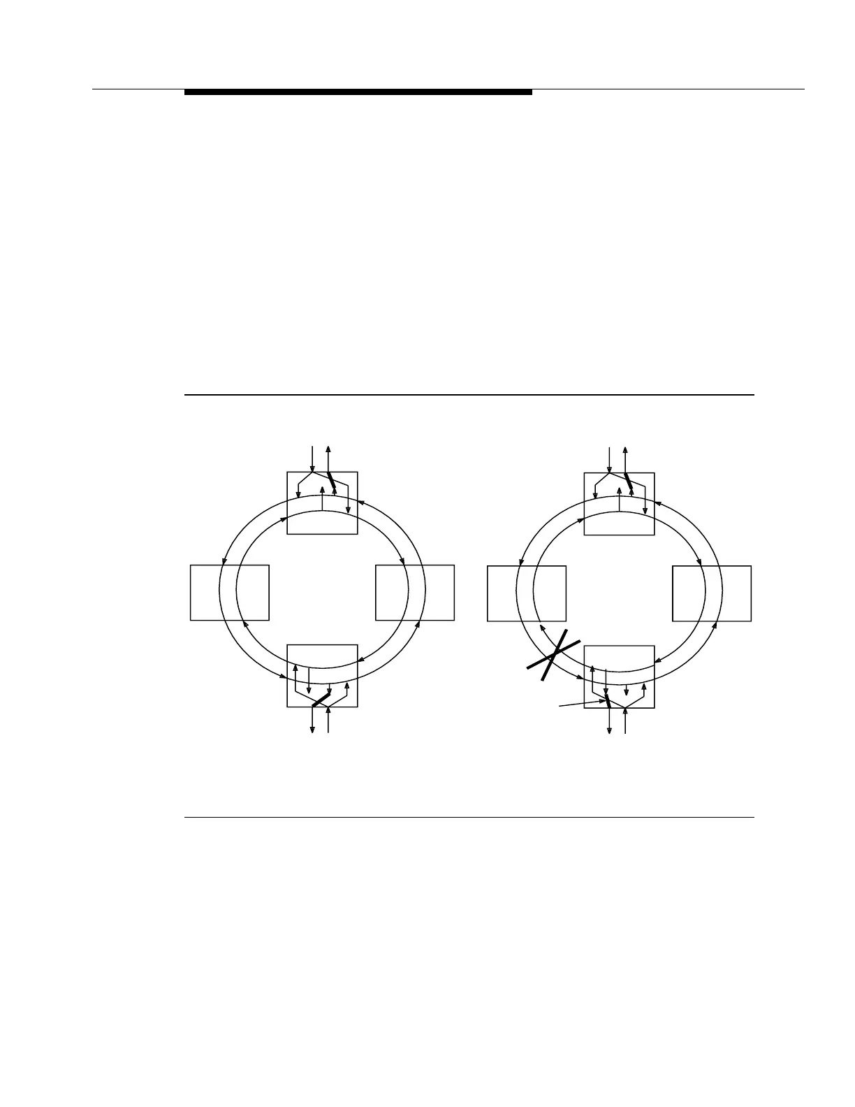
PathProtectionScheme 9
Path protection rings feed a SONET payload (STS or VT) from the ring entry
point, simultaneously in both rotations of the ring, to the signal's ring drop or exit
point as shown by traffic AC and CA in Figure 9-14(a). This duplication of the
signal that enters the ring is called a "head-end bridge." The node that drops the
signal from the ring monitors both ring rotations and is responsible for selecting
the signal that has the highest quality based on LOS/LOF, path AIS, LOP, STS/VT
unequipped, and STS/VT path BER performance. This function at the ring exit
point is called a "tail-end switch." Path switching is non-revertive. All detected
hard failures (LOS, LOF, LOP, line AIS, or STS-1 path AIS) and in VT path
switched rings, an STS-1 path signal failure based on BER or an STS path
unequipped results in path AIS insertion in the outgoing signals. This allows the
drop node to detect VT path failures and select the good path.
Figure 9-14. Path Protection Switching
Node C
Node A
Node BNode D
AC
CA
(a.) Normal Operation
Node A
Node BNode D
AC
CA
AC
CA
Node C
AC
CA
(b.) Path Failure
SWITCH
MADE