363-206-285
Technical Specifications
10-44 Issue 3 June 2001
When using universal optical buildout attenuators for OLIUs equipped with Universal
Optical Connectors (for example, 22G-U and 22D-U), the buildout must have the
same type fiber on both sides, that is, single-mode to single-mode or multimode to
multimode. The buildout must also match the mode of the fiber. Therefore, when a
single-mode jumper is used, the buildout would be on the transmit side (OUT) of the
OLIU and when a multimode jumper is used, the buildout would be on the receive
side (IN) of the OLIU. When using in-line attenuators for non-U OLIUs, place the
attenuator in the bay frame PANDUIT. Make sure that the mode type of the
attenuator matches the mode of the fiber to ensure proper attenuation.
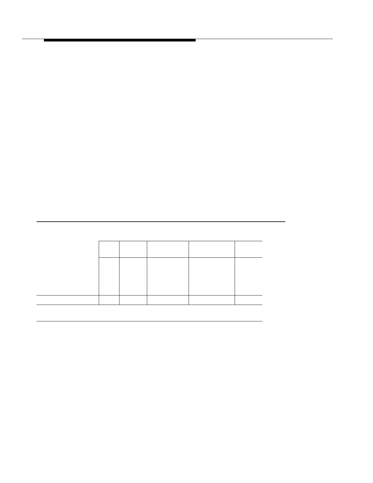
Table 10-18 details the maximum link budgets for each pairing of OC-3 rate OLIUs
when operating on single-mode (SM) fiber. These numbers give the maximum
attenuation acceptable for proper operation of each transmitter/receiver pair. The link
must have no more than this much attenuation either from fiber loss, splice loss,
connector loss, external attenuators or a combination of these or the link will not
operate properly. The maximum link budgets for SM fiber were calculated using the
following margins:
■ Optical Path Penalty (dB) 1.0
■ Connector Loss (dB) 1.5
Table 10-18. OC-3 Rate OLIU Mixes - Maximum Link Budgets for SM Fiber (dB)
Transmitter
Receiver
22F
22G-U∗/
22G2-U
22D-U
(Ctrld. Env.)
22D-U
(Unctrld. Env.)
22G3-U
22G4-U
22F 15.0 15.0 14.8 12.8 15.0
22G-U∗/22G2-U 23.0 23.0 22.8 20.8 23.0
22D-U (ctrld. env.) n/a n/a n/a n/a n/a
22D-U (unctrld. env.) n/a n/a n/a n/a n/a
22G3-U/22G4-U 25.0 25.0 24.8 22.8 25.0
*
The LAA10 FT-2000 OC-3 Optical Interface has the same optical loss budget as
the 22G-U and therefore should follow the same optical mixing rules
.