Operating elements for crane operation
9.2 Short description of the operating elements
9 - 100 3 112 xxx en Operating Manual GMK6300L
xx.xx.xxxx
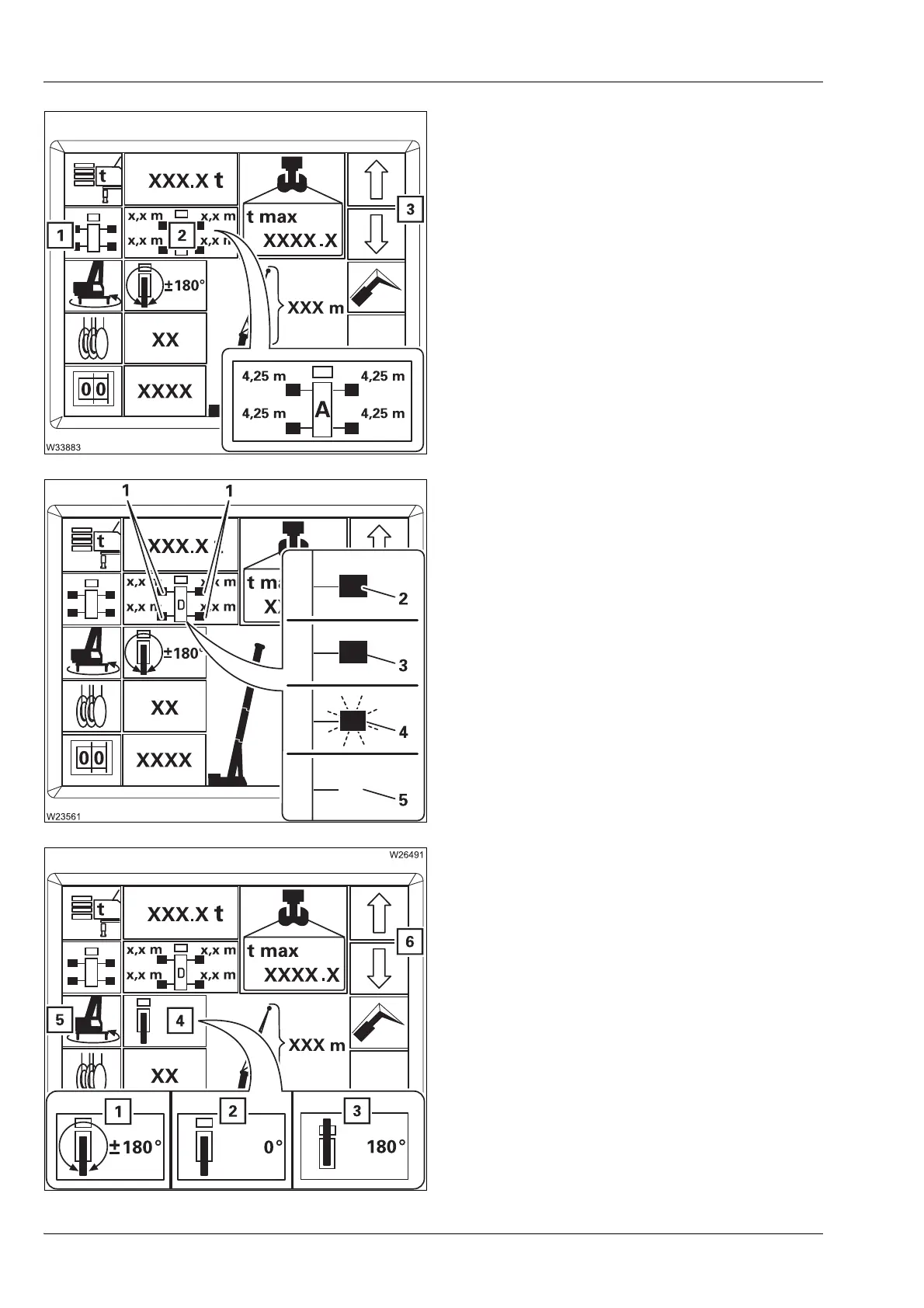
Enter outrigger span
– Input mode on
Press button (1) once – symbol green
– Input
In input mode press button (3) once – on
display (2) next outrigger span.
à p. 11 - 24
Outrigger span monitoring display
The display (1) is identical for all outrigger
beams (2).
With displays (4) and (5) an error message is
displayed after applying the rigging code;
à p. 11 - 24.
Enter slewing range
– Input mode on
Press button (5) once – symbol green
– Input
In input mode, press button (6) once – next
permissible slewing range on display (4)
à p. 11 - 24
A 8.70 x 8.50 m (28.5 x 27.9 ft)
B 8.70 x 7.40 m (28.5 x 24.3 ft)
C 8.70 x 6.30 m (28.5 x 20.4 ft)
D 8.70 x 5.00 m (28.5 x 16.4 ft)
M 8.70 x 2.71 m (28.5 x 8.9 ft)
(3) Illuminated – the required outrigger span
is rigged
(4) Flashes – the required outrigger span is
not rigged
(5) No display – the current outrigger span is
not permitted
1 360° slewing range
2 Working position 0° to the rear
1)
3 Working position 180° to the front
1)
1)
To accept, switch off the slewing gear
 Loading...


