7-3
Electrical Shock Hazard
Disconnect power before servicing.
Replace all parts and panels before operating.
Failure to do so can result in death or electrical shock.
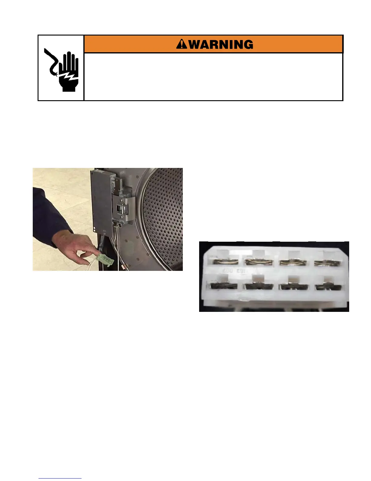
TESTING DOOR LOCK COMPONENTS FROM
DOOR LOCK WIRE HARNESS PLUG
Disconnect the door lock wire harness
connector at the door lock assembly.
To test the Door Unlock Solenoid Coil:
Touch one test lead to pin #1.
Touch other test lead to pin #2.
The meter should indicate 7000 to 8000 Ω.
To test the Door Lock Solenoid Coil:
Touch one test lead to pin #3.
Touch other test lead to pin #4.
The meter should indicate 7000 to 8000 Ω.
To test the Bi-metal:
Touch one test lead to pin #5.
Touch other test lead to pin #6.
The meter should indicate 17,000 - 18,000 Ω.
To test the Door Lock Switches:
Touch one test lead to pin #7.
Touch other test lead to pin #8.
With the door closed or locked, the meter
should indicate continuity (0 Ω)
With the door open, the meter should indicate
open circuit (infinite Ω).
NOTE: If door switch readings are not what
is expected, determining which switch is faulty
will require individual switch diagnostics within
the lock assembly.
Pin 1
Pin 8 Pin 7 Pin 6 Pin 5
Pin 4 Pin 3 Pin 2
 Loading...