7-18
Electrical Shock Hazard
Disconnect power before servicing.
Replace all parts and panels before operating.
Failure to do so can result in death or electrical shock.
TESTING TEMPERATURE SENSOR
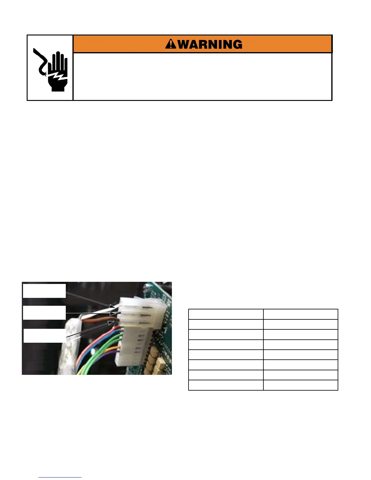
The temperature sensor cable is connected at
the upper right hand side of the control board
on a 3 pin connector labeled “T1” and it is
wire-tied along the cabinet with the rest of the
wire harness until it reaches the bottom left
rear of the outer tub, where it is inserted and
held in place with a compression tting.
The 3 pins on the T1 connection of the washer
control board are as indicated below:
Top pin: Negative (-)
Middle pin: Shielded wire
Bottom pin Positive (+)
The Thermistor within the sensor is connected
across the top pin (negative) and the bottom
pin (positive). Measuring at the control board
“T1” with the sensor connector disconnected,
the normal DC voltage measured from top pin
to bottom pin = approximately 5 volts.
•
•
•
QUICK TEST:
Disconnect the Temperature Sensor from
“T1 on the control board.
Check in Status Screen for temperature
reading. Temperature reading in the display
should be 255(F).
Short the bottom pin and the top pin
together.
Check in Status Screen for temperature
reading. Temperature reading in the display
should be 34(F)
Temperature sensor plug at “T1” on the
control board should be a three wire plug
with white (top), black (middle) and brown
(bottom) wires coming into it.
•
•
•
•
•
Degree F: (C) Ohms:
50 (10) 880
70 (21.1) 955
90 (32.2) 1055
110 (43.3) 1145
130 (54.4) 1245
150 (65.6) 1340
170 (76.7) 1440
Negative (-)
Positive (+)
Shielded



 To Next Page