4-6
Incoming
Power
Door
Lock
Output
Wiring
Motor
Control
Temperature
Sensor
Water
Level
Sensor
Supply
Signals
8mm
Nuts
Key Pad
Ribbon
Cable
Input
Circuit
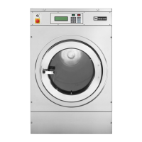
Raise the top of the washer (See page 4-2).
Disconnect all the wire connectors.
Snip the wire tie and disconnect the water
level sensor hose.
Remove two 8mm hex nuts from the right
end of the control board.
1.
2.
3.
4.
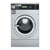
REMOVE CONTROL BOARD & MEMBRANE SWITCH - PN
Push on the right hand side of the board,
from inside the washer, and slide it to the
right to remove the control board membrane
switch assembly from the front of the control
panel.
Remove the seven #1 star head screws and
flat washers from the back side of the board.
Lift the control board off the membrane
switch.
TECH TIP: The EPROM chip must match
the board for the model. A new control board
does not come with an EPROM. If just the
board is to be replaced, remove the EPROM
from the old board and place it on the new
board (See page 4-7). A new EPROM can
be ordered and installed at the same time
the board is ordered if necessary.
5.
6.
7.
Electrical Shock Hazard
Disconnect power before servicing.
Failure to do so can result in death or
electrical shock.
Replace all parts and panels before
operating.