94 Panel Functions
_________________________________________________________________________________________
_________________________________________________________________________________________
Microplex logiJET TC8 Edition 1.2
Description of the Working Steps for the Reflex Sensor (Black Mark Sensor):
A) Start the printer in the Service Mode, compare section 7.2.3 (necessary for steps in section D).
Please go to [Paper Type ] in the printer menu structure:
Paper Menu\Paper Type\ select Black Mark
(use PREV or NEXT key, then ENTER)
C) Shift the Reflex sensor (R) to the position of your black marks
See section 7.2.1 Checking and Adjusting the Position of the Sensors
D) Sensor Current (CV value) adjusting
Please go to Sensor Test and select the subpoint Reflex:
Engine\Sensor Test\ select Reflex
The currently measured sensor level (contrast) is displayed.
Press the ENTER key again, after this 2 values are displayed:
Left VV = curr. measured sensor value (level) Right CV = reference value for sensor current.
CV is modifiable (and has an effect on the VV value).
Use the NEXT or PREV key to set the CV value. Approx. CV value:
Load paper into the sensor.
The sensor measured value (VV level) of the paper (not black mark)
should count less than 10%.
If the VV level is too high, increase CV (sensor current).
Put a black mark into the sensor area.
The sensor measured value (VV level) of the black mark should count
as possible more than 45 %.
If the sensor measured value (VV level) of black mark is too
low, the CV value should be decreased.
Higher black mark VV values than 45 % are more advantageous so
long as there is no rising above 10 % of the paper VV level.
Measure both sensor levels once again for Paper and Black mark.
(You need the two level values of your material for the following switching threshold adjustment)
Save the new current value (CV) using the ENTER key.
E) Sensor Switching Threshold adjusting
Please go to [Sync.Sens.Level ] in the printers menu structure:
Engine\Sync.Menu\Sync.Sens.Level
At the right the switching threshold value is displayed.
Use the NEXT and PREV keys to set the
switching threshold of the sensor to the
middle between the paper level and the
black mark level:
Save the new switching threshold
(ENTER key).
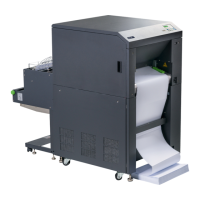
Graphical explanation for switching threshold setting:
Level
in %
Black mark
Mean value is to be used as Switching threshold
Paper
0
Hint:
The displayed
level value is
directly valid for
printers with a
threshold setting
range from 0 to
100%.
If your printer is
provided with a
threshold setting
range from 0 to
200%, the setting
value has to be
doubled.