7-18 Structure and Assembly/Disassembly
Figure 7-19 Disassembly of the IO Board
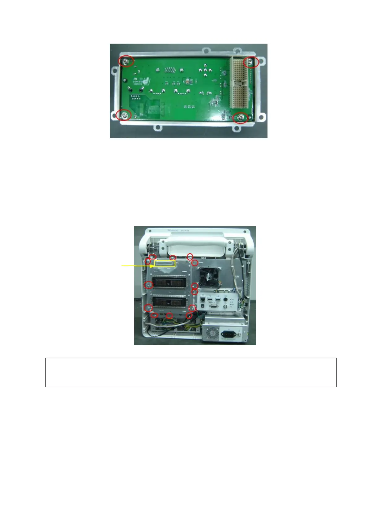
7.4.4 Probe Board
1. Remove rear cover assembly of the main unit (referring to 7.4.1 the 1~4 step)
2. After removing panhead screws with washers (13 M3X6) which are installed on the rack of
the main unit rear cover and cutting off cable ties fixed on the probe board, you could remove
the probe board assembly backward.
Figure 7-20 Disassemble the Probe Board Assembly
Make sure that you could pull out and push into the probe board sockets vertically
when pulling out and assembling the probe board assembly on the position of the
handle.
3. After removing panhead screws with washers (9 M3X6) used to fix the probe board, you
could take out the probe board.

 Loading...


