Hardware Principle 4-11
4.2.7 Control Panel
5 status
indicators
TGC board
Trackball
Functional
button
Single-
encoder
board
Key
scan
LED
backlight
driver curcuit
LED
backlight
USB
Interface
chip
ADC curcuit
Buzzer
Buzzer driver curcuit
Main
control
Trackball
scan
TGC
scan
PWM generating
curcuit
FPGA
Control panel PCBA
Main
board
USB
+12V
+5V
Double-
encoder
board
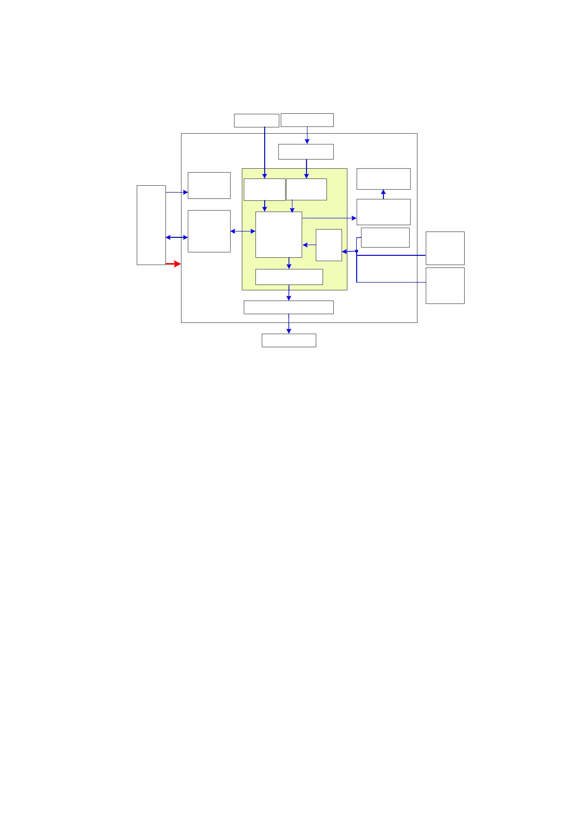
Figure 4-10 Principle Diagram of Control Panel
The control panel PCBA is the core of the control panel which comprises control panel PCBA,
trackball, TGC board, encoder board and buzzer.
Function describes as following:
FPGA is regarded the control panel as a main controller , key, single/dual-encoder,
trackball and TGC.ect are basically scanned by FPGA; Key LED backlight and buzzers
are both controlled by FPGA, and only when FPGA is normal can key LED backlight be on.
Five indicators on the control panel are directly drived by interior of main unit.
The control panel communicates with the CPU module by USB ports.

 Loading...


