Hardware Principle 4-9
4.2.5 Ultrasound System Indicator
CPU
Module
Main board
Power
status
indicator
Power-on status
indicator
Battery status
indicator
AC supply status
indicator
Standby status
indicator
Power
management
FPGA
HDD indicator
driver
5VSTB_CPU
Control panel
+12V
+5V
3.3V
ARM
driver
Power supply
module
IO Board
driver
driver
driver
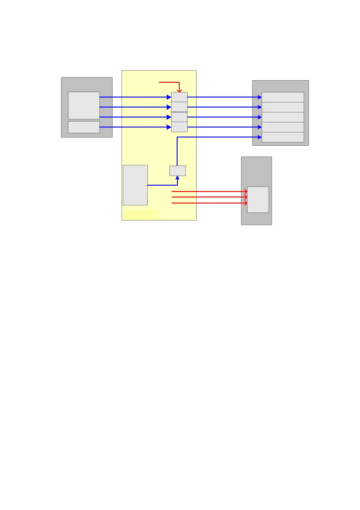
Figure 4-8 Principle Diagram of Ultrasound System Indicator
Function describes as following:
There are four power status indicators on the IO panel: three are used for indicators of
+12V, +5V and 3.3V output on the DC-DC power board, the other one is used for reserved
indicator.
There are five indicators on the control panel, in which power-on status indicator is below
the power button.
AC power-on status indicator control is output by the power management FPGA on the
power module.
The hardware indicator control is output by CPU.
The status indicator of battery are controlled by the battery management ARM on the
power module which driven by 5VSTB on the main board.
The status indicators of power-on and standby are both generated by the battery
management FPGA in the power module and driven by 5VSTB on the main board.

 Loading...


