4-4 Hardware Principle
4.2.1.2 Probe Board of Z5 Series
High-voltage
switch
Relay
CPLD
Transducer
socket A
(96 pin)
Relay drive
circuit
Transducer
socket B
(96 pin)
POUTA[80:1]
POUTB[80:1]
RELAY_EN
BOARD_ID[7:0]
POUT[80:1]
driver
BOARD ID
Probe board of Z5 series
RELAY_PWR_EN
PRB_B_ID[6:1]
PRB_A_ID[6:1]
VDD
Driver
High-voltage
switch control
signal
+5V
+95V
-95V
Probe board
control signal
LC
LDO
D+3V3
A+5V
A+95V
A-95V
PRB_B_ON
VDD
driver
driver
Driver
driver
PRB_A_ON
OE_N
PRB_A_ID[6:1]
OE_N
PRB_A_ID[6:1]
PRB_B_ON
PRB_A_ON
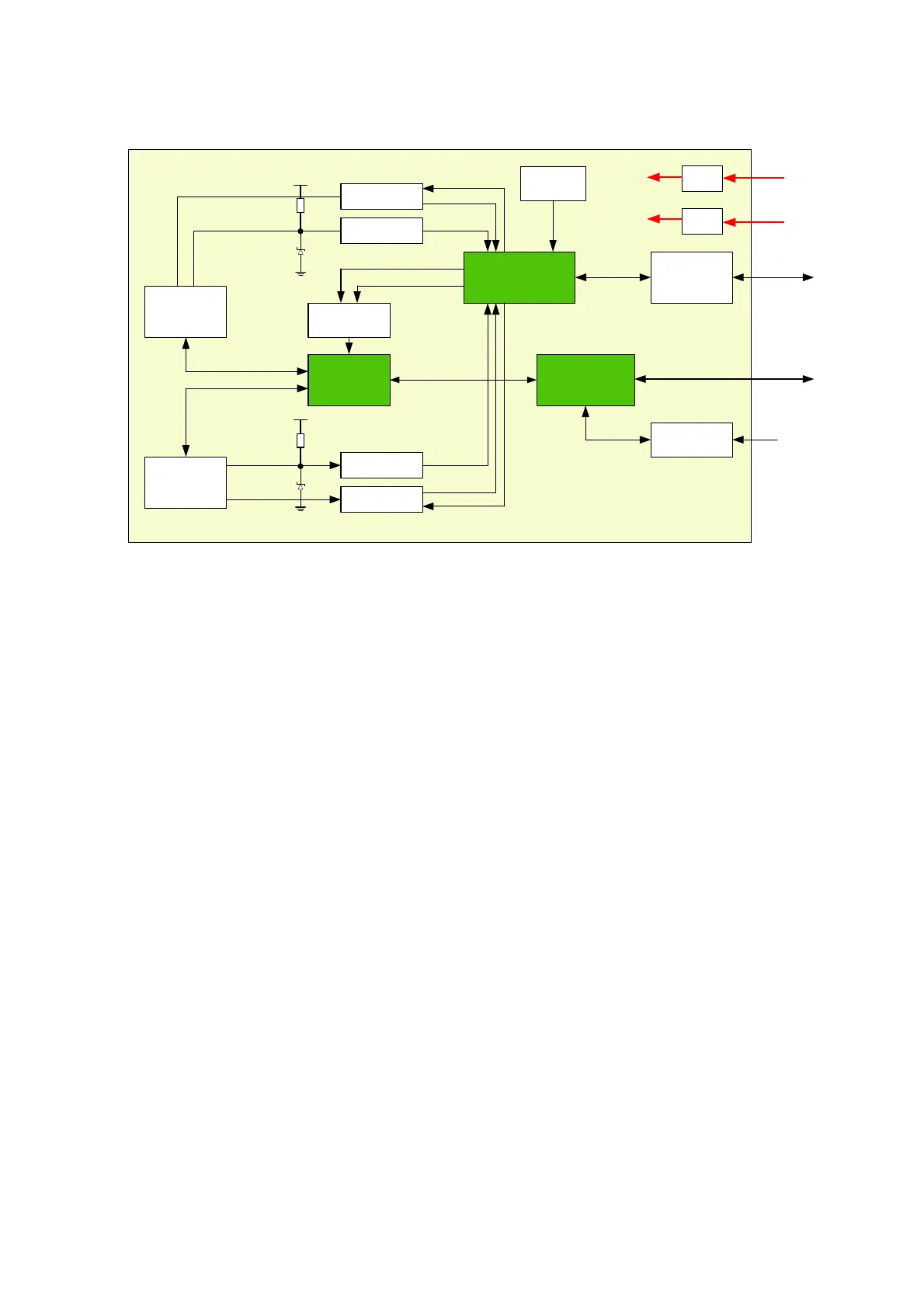
Figure 6-3 Principle Diagram of Z5 Series’ Probe Board
The function of Z5 series probe board describes as following:
The ultrasound signal are transferred from 32-physical channel to 80-array by the
high-voltage switch on probe board.
Probe information could be obtained by probe board via reading probe online signal and
probe ID.
Support two 80-pin probes, and only one probe could be chosen to work by relay switching
on probe board.
4.2.2 Main board
The main board could be divided into two parts: front-end of the main board and back-end of the
main board.

 Loading...


