4-12 Hardware Principle
4.3 Power System
AC Input
100-240V~,50/60Hz
Battery
14.8V,6600mAh
DC Output 19V/3.95A
Power supply module
Power
management
FPGA
DC-DC power board
AC-DC power board
PWR_BTN_N
Main board
Control
panel
System
monitor
module
Temperature signal
CPU
module
ARM
Multifunction
FPGA
ARM control signal
POWER
I2C
PHV
AD DA
Closed signal of the control panel
AC in place
Power on/off control signal
Status indicator
control signal
12V、5V
battery in place
Fan
Fan monitor
12V
Display
12V
Battery
connecting
board
I2c
battery
in place
14.8V,
6600mAh
Status indicator
Restart automatically
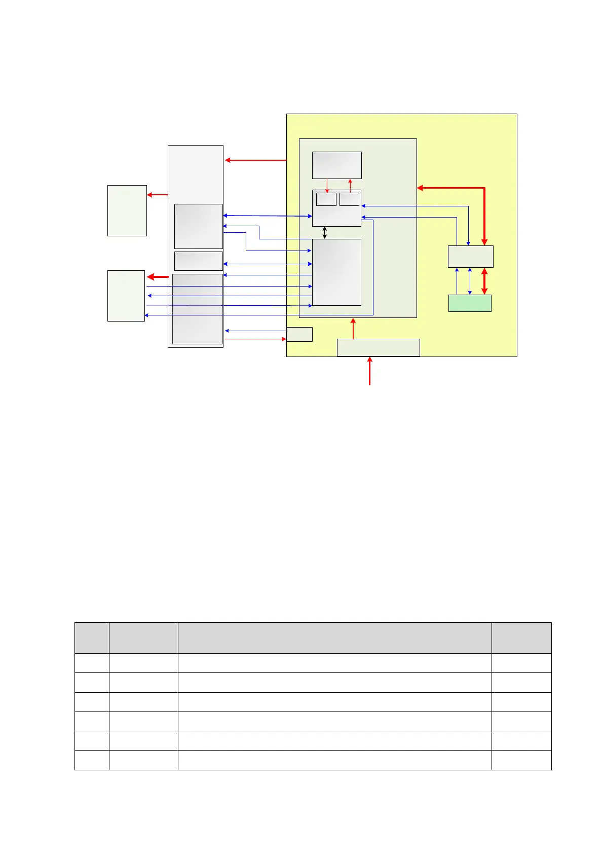
Figure 4-11 Block Diagram of Power System
The power supply configuration of the system describes as following:
The power supply module can be divided into AC-DC power board, DC-DC power board,
battery and battery connecting board.
High-voltage programmable ARM and power management FPGA are on the DC-DC power
board.
Power output by the power supply module is transmitted to main board, and then it is output to
control panel and display by the main board.
Battery is connected to the DC-DC board via the battery connecting board and connecting
cable of BTB sequentially.
4.3.1 Power Output of the Power Supply module and
Supporting Function Distribution
Support circuit module or function
CPU module, Display, Fan, Control panel
HDD, Control panel, Front-end of main board, Probe board
Front-end of main board, Back-end of main board, Display

 Loading...


