3-8 System Installation
Before inserting the connector into the probe port, inspect the connector pin. If the pin is
bent, do not use the probe until it has been inspected / repaired / replaced.
3.4 Installing Peripherals
For the models of the supported peripherals, please refer to “2.1.3 Supported Peripherals”.
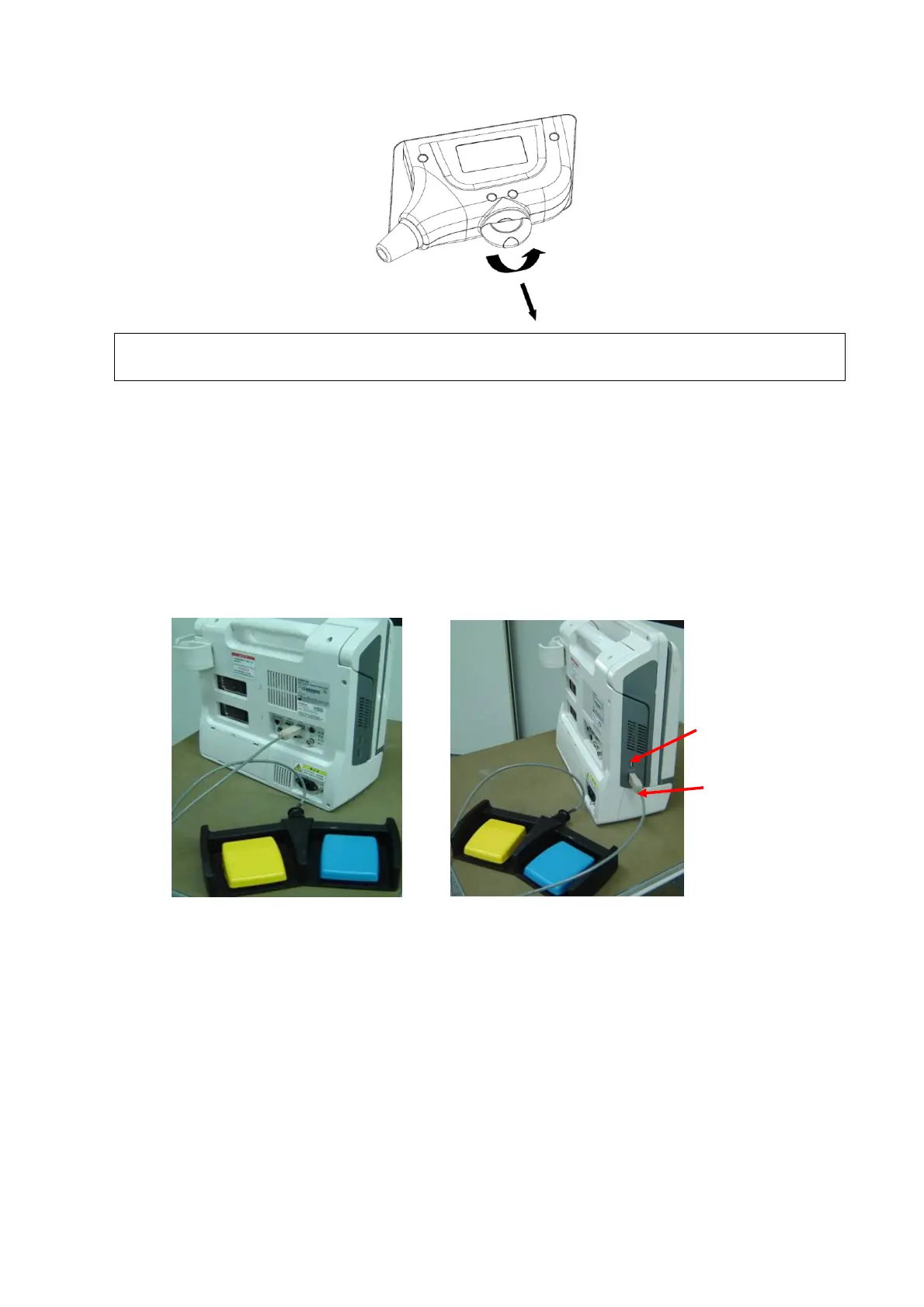
3.4.1.1 Footswitch Installation
1. Connecting: Take 971-SWNOM as an example: insert the USB connector to the system
available USB ports (on the left and rear of the machine).then the footswitch can be used
directly.
2. For settings of footswitch, please refer to 3.5.3 system preset.
Figure 3-5 Footswitch connection
3.4.2 Video Printer Installation
Analog video printer:
1. Connect one end of the signal line to the Video In interface of the printer, and the other to
the video output port in the ultrasound system IO panel.
2. Connect the Remote control line to the Remote interface in the ultrasound system IO
panel.
3. Insert the power cord to a power supply receptacle that is well grounded.

 Loading...


