Hardware Principle 4-7
FPGA on the power supply module implements the machine power on/off by the switch
signal.
Standby indicator, AC present indicator and working status indicator on the control panel
are output by FPGA.
The control panel implements communication with CPU module by USB.
CPU output the audio signal to the speaker on the front cover of main unit, via audio coder
and audio amplifier.
4.2.3 IO Broad
Main Board
Video S-Video Remote
Multifunction FPGA
Video Encoder
Control
Data
VGAUSB Ethernet
CPU module
System
Monitor
Circuit
Status Indicator
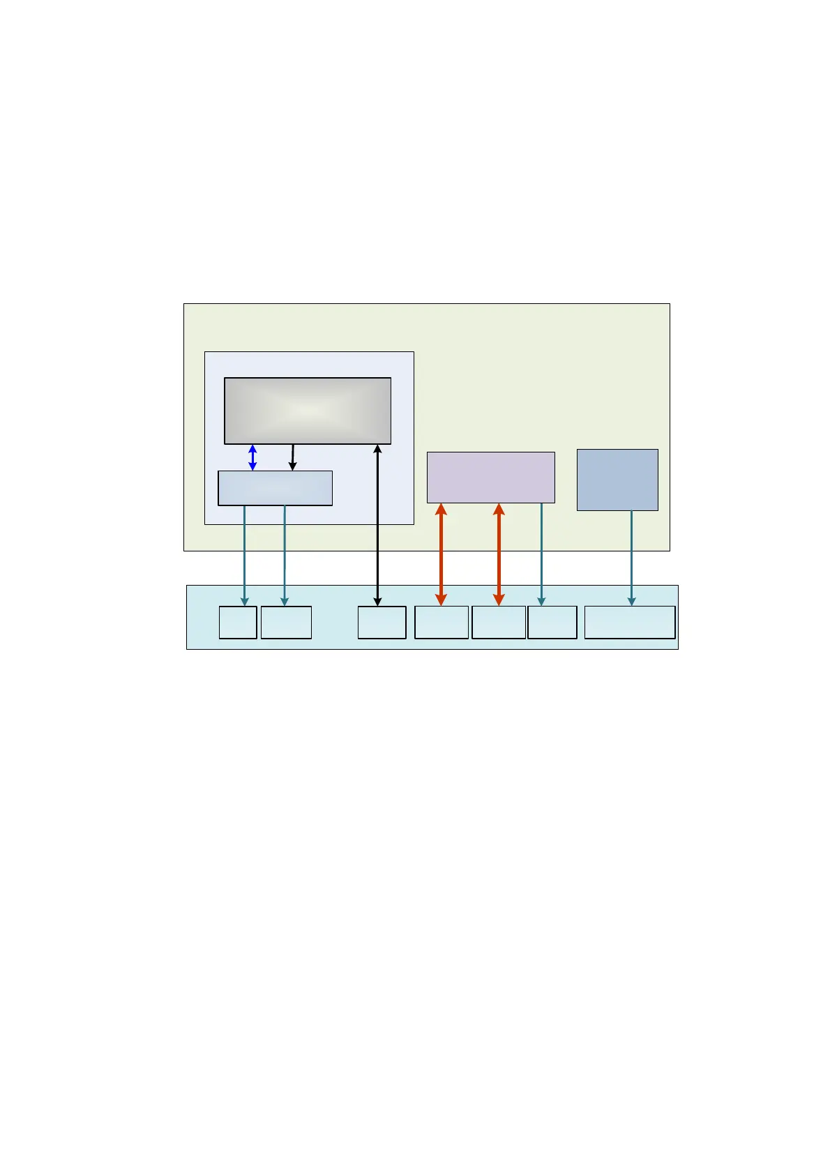
Figure 4-6 Principle Diagram of IO Board
IO board is connected to the main board via connectors in order to implement the user
interface function and indicate if the power is normal.
IO board supports Video and S-Video, and the two channels of signal get by Video
Encoder driven by Multifunction FPGA.
IO board supports REMOTE signal, which is obtained by Multifunction FPGA on the main
board.
USB signal, Ethernet signal and VGA signal on the IO board are obtained by CPU module
output.
Status indicators of IO board respectively refers to12V, 5V and 3.3V powers are normally
working.

 Loading...


