4-6 Hardware Principle
The CPU module communicates with the probe board via BF FPGA.
4.2.2.2 Back-end of Main Board
IO board
PCIE
PHY
PCIE X1
HDD
VGAUSB
Video S-Video Remote
Ethernet
Multifunction
FPGA
LPC
LVDS
USB
CPU Module
SATA
+12V
LVDS
Display
SMBUS
Control signal of the inverter
Video
Encoder
Control
USB
Lateral
USB
System monitor curcuit
Power Supply Module
ARM control signal
HDD Indicator
Control signal of parameters board
Control panel
Main Board
Status indicator
5V
12V
3.3V
POWER
12V
5V
5VSTB
Status indicator
Power_BTN_N
Closed status indicator on the control panel
ARM
Power
Management
FPGA
Control signal
Power on/off signal
Data
Audio
Codec
Audio
Power
amplifier
Speaker
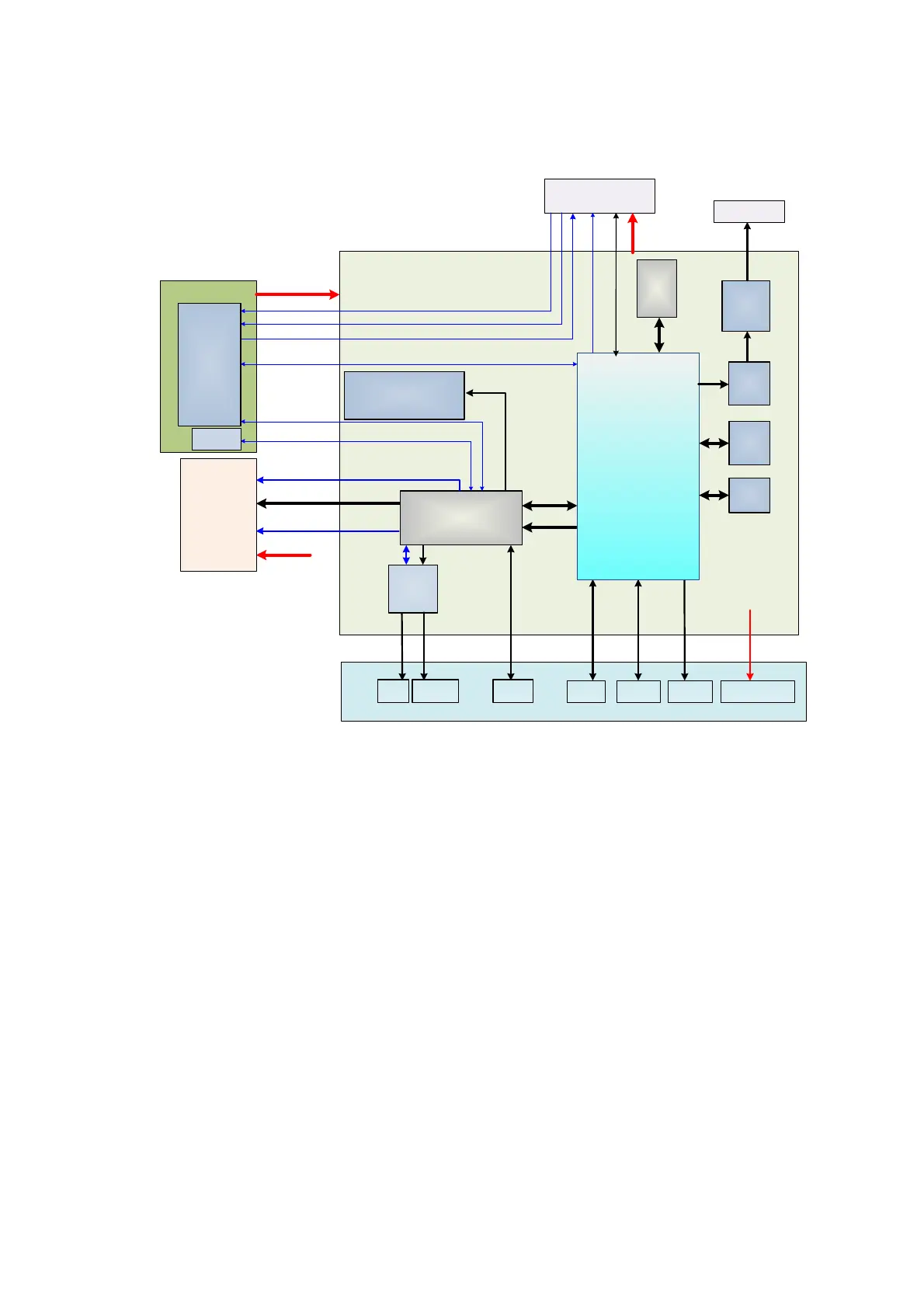
Figure 4-5 The Schematic Diagram of Back-end of Main Board
Back-end of main board is the core of back-end ultrasound system, which mainly includes
back-end of main board, CPU module, IO interface board, monitor assembly and control panel.
Mainly implements display interface, user's operation interface, power module controlling interface
and all kinds of Peripherals Supported interface.
Also provides system monitoring, running status of the monitor system, indicator of system
status and running status of the indicating system via LED.
Function describes as following:
Back-end of main board connects to front-end of main board via PCIE PHY.
The USB on the lateral of Main board is the output of the CPU module.
The relevant signal in HDD of the main board is output of the CPU module.
Back-end of the main board MUL FPGA implements display ports, it also supports display
assembly, video and s-video interface of IO board.
Multifunction FPGA on the back-end of the main board is to implement the REMOTE port
on the IO panel.
The CPU module implements interfaces including USB, Ethernet and VGA on the IO
board.
System monitor circuit connects Multifunction FPGA though smbus.
Multifunction FPGA communicates with ARM by serial port to control transmission
high-voltage, and also implements ARM update by serial port.

 Loading...


