Structure and Assembly/Disassembly 7-19
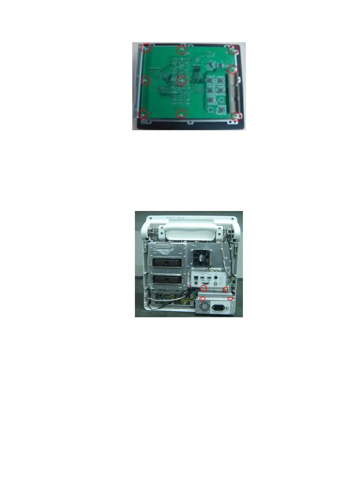
Figure 7-21 Disassemble the Probe Board
7.4.5 Main Board and CPU Module
1. Remove rear cover assembly of the main unit (referring to 7.4.1 the 1~4 step)
2. Remove panhead screws with washers (4 M3X6) which are fixed on the main unit, take out
the power shielding board and then pull out two cables connecting the main board to the
power module assembly.
Figure 7-22 Disassemble the Main Board Assembly (1)
3. Remove the probe board assembly (referring to 7.4.4 the 2
nd
step) and the IO assembly
(referring to 7.4.3the 1~4 step)
4. Remove panhead screws with washers (8 M3X6) fixed on the main unit box, and take out
separating board assembly of the main unit (including separating board of the main unit,
heightening washer of fan and fan on the rear board).

 Loading...


