System Installation 3-13
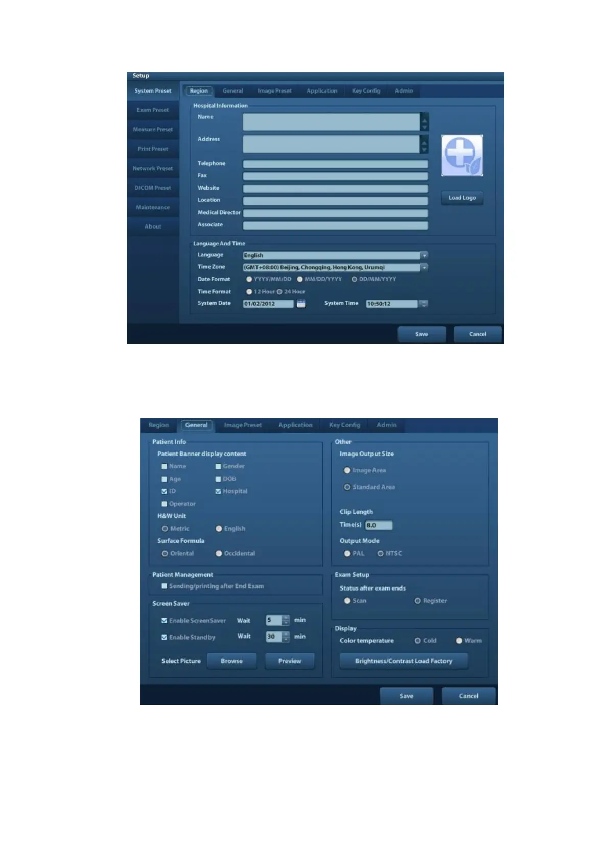
In the Region page, set the system language, date format, date, time and hospital related
information, etc.
General
Click <System Preset> to enter:
In this page, set the time of standby, brightness/contrast and color temperature of display,etc.
Key Config

 Loading...


