12
Installation & Wiring
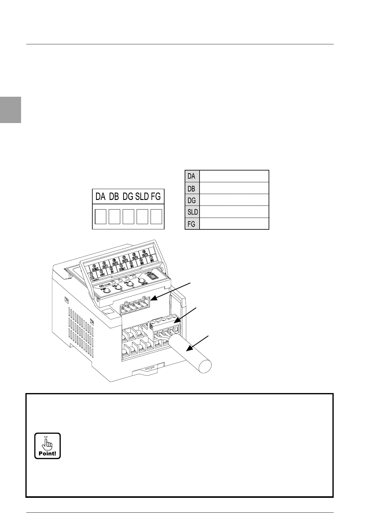
2-6. Connection of CC-Link interface
The cable only for CC-Link is wired to the attached connector for CC-Link, and connected
as shown in the figure below.
●
For connection of CC-Link cable, use a twisted pair cable line with shield (Cable only for
CC-Link) and connect a shield with SLD terminal.
●
Stripped length of electrical cable tip is 6 mm.
●
The tightening torque of terminal screws on the terminal block is 0.6 N・m.
●
When you connect with this instrument, please check the direction of upper/lower sides
of the connector, and insert until it bumps.
CC-Link interface connector
Attached CC-Link interface
connector
Cable only for CC-Link
interface.
Signal line DA side
Signal line DB side
Signal ground
Shield
Frame ground
• Attached connector for CC-Link : MSTB 2,5-ST-5,08 AU(by PHOENIX CONTACT)
• As to the termination, connect the terminating resistance of 110 Ω with the CC-Link
connector which is the furthest from PLC as possible.
• The connecting cable must use the cable only for CC-Link.
• Refer to the [Construction and specification of network system] from the latest
version of CC-Link Cable Wiring Manual publishe
d by CC-Link Partner Association
about communication speed and cable length.
• [SLD] and [FG] are connected internally.
• Please refer to [5. Applied standard] in [Safety Precaution] about the grounding to
comply with CE Standard.