EasyManua.ls Logo

Minebea CC-Link CSD-892-73 - User Manual

Minebea CC-Link CSD-892-73
159 pages
Print Icon
To Next Page IconTo Next Page
Loading...
EN294-1540
General
Installation/Wiring
Changeover of mode
Calibration
Setting of Function
Setting of Comparator
Check mode
CC-Link interface
USB (RS-232C) interface
Trouble shooting
Specifications & others
CSD-892-73
Instruction Manual
DIGITAL CONVERSION MODULE
Measuring Components Business Unit
Minebea Co., Ltd.

Table of Contents

Questions and Answers

  • K
    Karen BrowningAug 18, 2025
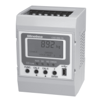
    What to do if the load display on my Minebea CC-Link CSD-892-73 Control Unit doesn't show a normal value?
    • G
      gonzalezericAug 19, 2025
      First, check if the load cell cable is correctly connected. Also, ensure that the calibration is executed. If not, proceed with the calibration. Another possible cause is an abnormal bridge voltage. Measure the voltage between A-C after shortening between A-F and A-C without connecting a strain gauge based transducer. The specification value should be DC5 V ± 0.25 V. You can also confirm the input from strain gauge based transducer by the monitoring mode.
  • J
    Justin LamAug 21, 2025
    Why is communication not normal on my Minebea CC-Link CSD-892-73 Control Unit?
    • J
      jeffreylopezAug 21, 2025
      Check that the cable for the CC-Link interface is correctly connected and that its length is within the regulation provided by the CC-Link society. Also, verify that the terminating resistance is correctly connected and that the number of occupied stations, the station number, the baud rate, and the method of 32-bit data representation are correctly set.
  • K
    Kelly BaileyAug 23, 2025
    What to do if the external control output doesn't operate on my Minebea Control Unit?
    • M
      maria59Aug 25, 2025
      First, verify that the equipment is correctly connected and the allocation of the external control output is correctly set. Also, check if the setting of measurement value / comparison value is within the range of setting. Ensure that the voltage and the electric current for an open collector are used within the specification value: Vce = DC35 V, Ic = DC50 mA max.
  • J
    Justin WangAug 26, 2025
    Why is the display not steady on my Minebea CC-Link CSD-892-73?
    • X
      xbrownAug 26, 2025
      Check if the weight on the measurement section is steady. Also, verify that the bridge voltage is normal by measuring the voltage between A-C after shortening between A-F and A-C without connecting a strain gauge based transducer; the specification value should be DC5 V ± 0.25 V. Confirm that the input from the strain gauge based transducer is steady using the monitoring mode. If necessary, set various filters.
  • B
    Brian NunezAug 28, 2025
    How to fix abnormal communication via USB interface on Minebea Control Unit?
    • C
      Christian AlvarezAug 28, 2025
      Ensure that the USB driver is installed on the host side and the port is normally recognized. Verify that the length of the USB cable is within the regulated 5 meters. Also, confirm that the command mode and the stream mode are correctly set.
  • E
    elizabeth67Aug 30, 2025
    What to do if the external control input doesn't operate on my Minebea CC-Link CSD-892-73 Control Unit?
    • M
      Matthew CamposAug 30, 2025
      Check that the equipment is correctly connected and the allocation of the external control output is correctly set. Ensure that a signal of 50 ms or more is input for the pulse input, or that the signal input at the level input of 50 ms or more continuously.
  • K
    Karen ComptonSep 1, 2025
    Why is the display not lit on my Minebea CC-Link CSD-892-73?
    • J
      Jeffery WhiteheadSep 1, 2025
      Verify that the power supply voltage is within the permissible range (DC20.4 V ~ DC27.6 V) and that the power supply cable is correctly connected.
  • J
    John MyersSep 4, 2025
    Why does the backlight of the LCD disappear on my Minebea CC-Link CSD-892-73?
    • D
      Debra Williams MDSep 4, 2025
      Check that the power supply voltage is within the permissible variable range (DC20.4 V ~ DC27.6 V). Also, verify that the ON time of the backlight for the liquid crystal is set.
  • B
    brooke08Sep 6, 2025
    What to do if the key operation is not accepted on my Minebea Control Unit?
    • R
      rjonesSep 6, 2025
      Check if either an individual key locking or the batch key locking is effectively set.
  • J
    janice66Sep 8, 2025
    What to do if the simple calibration function is not accepted on my Minebea CC-Link CSD-892-73 Control Unit?
    • J
      Jasmine ShermanSep 8, 2025
      Check if the simple calibration lock is set to turning on.

Summary

General Information

Product Manual Overview

Manual Marks and References

Explanation of symbols and references used in the manual for safety.

Safe Operation Guidelines

Location of Installation

Guidelines for selecting a suitable installation environment and location.

Instrument Installation

Power and Usage Instructions

Power Supply Precautions

Information and precautions regarding the instrument's power supply.

General Usage Instructions

General instructions and guidelines for using the instrument.

Conformity Standards

Revision History

Instrument Components and Functions

Front Panel Overview

Description of the components and indicators on the front panel.

Front Panel Parts

Details on the terminal blocks and connectors on the upper and lower parts.

Installation and Wiring

Instrument Operation

Mode Changeover Procedure

How to switch between the different operating modes of the instrument.

Calibration Procedures

Fine Adjustment of ZERO and SPAN

Steps for fine-tuning the zero and span calibration values.

Digital Linearization Process

Process for applying digital linearization to reduce measurement error.

Zero-Only Calibration

Procedure for re-calibrating the zero point when tare changes.

Simple Calibration Method

Method for quick setup and calibration of the instrument.

C Function Mode Settings

C Function Data Operations

Details on various operations controllable via C function data.

Decimal Point Display Setting

Setting the position of the decimal point in the display.

A;D Sampling Rate Configuration

Configuration of the Analog-to-Digital sampling rate.

Overload Display Conditions

Setting how overload conditions are displayed.

Comparison Display Synchronization

Synchronizing comparison operations with display or sampling.

Unit Selection

Selecting the measurement unit for display.

Zero Set Function

Function to set the current reading as the zero point.

Zero Tracking Function

Function to compensate for gradual zero drifts.

Zero Tracking Time Width

Setting the duration for ZERO tracking activation.

Power-On Zero Adjustment

Automatic zero adjustment upon power-on.

Tare Weight Cancellation

Procedure to cancel tare weight and set net value.

Data Storage Location

Selecting storage location for settings (RAM or EEPROM).

Function Mode Operations

Operations by Function Data

Operations controlled by function data settings.

Digital Filter Settings

Applying digital filtering to smooth readings.

Analog Filter Settings

Using analog filtering to reduce input noise.

Stabilization Filter Settings

Enhancing reading stability by increasing digital filter effect.

Key Lock Functionality

Preventing unintended key presses by locking functions.

Stability Detection

Detecting when the measured value has stabilized.

Hold Function

Function to retain the current measurement or comparison result.

External Control I;O

Managing external inputs and outputs for control.

External Control Input Settings

Configuring external input functions.

S Function Mode

Measurement Mode

Check Mode Operations

CC-Link Interface

General CC-Link Information

General introduction to the CC-Link interface.

CC-Link Interface Features

Key features of the CC-Link interface.

CC-Link Interface Specifications

Technical specifications for the CC-Link interface.

Occupied Station Configuration

Setting the number of occupied stations for CC-Link.

PLC Memory Explanation

Explanation of PLC memory allocation for CC-Link.

CC-Link Address Map

Mapping of addresses for CC-Link communication.

Station Number Settings

Setting the station number for CC-Link communication.

Baud Rate Configuration

Configuring the communication speed (baud rate) for CC-Link.

32-Bit Data Indication Method

Method for indicating 32-bit data in CC-Link communication.

CC-Link Interface Calibration

Performing calibration via the CC-Link interface.

Operation Methods

Writing Set Values

How to write set values from the master station.

General Command Operations

Performing data operations using general commands.

Troubleshooting Guide

Basic Troubleshooting Steps

General troubleshooting steps and checks.

Error Display Information

Warranty and Repair Information

Instrument Repair Process

Information and procedures for instrument repair.

Component Lifespan

Expected lifespan of instrument components.

Display Character Patterns

Function Setting Reference Table

Minebea CC-Link CSD-892-73 Specifications

General IconGeneral
BrandMinebea
ModelCC-Link CSD-892-73
CategoryControl Unit
LanguageEnglish