4
SETUP AND PROCEDURES BEFORE OPERATION
4.3 Part Names
4 - 5
1
OVERVIEW
2
SYSTEM
CONFIGURATION
3
SPECIFICATIONS
4
SETUP AND
PROCEDURES
BEFORE OPERATION
5
UTILITY PACKAGE
(GX CONFIGURATOR-
AD)
6
PROGRAMMING
7
ONLINE MODULE
CHANGE
8
TROUBLESHOOTING
* 1 Check the error code for details.
* 2 When the module is mounted on a MELSECNET/H remote I/O station, the RUN LED stays off until
a data link starts normally, even after the power is turned on. The RUN LED turns on once a data
link starts.
When two or more errors have occurred, the latest error found by the A/D
converter module is indicated with the LED.
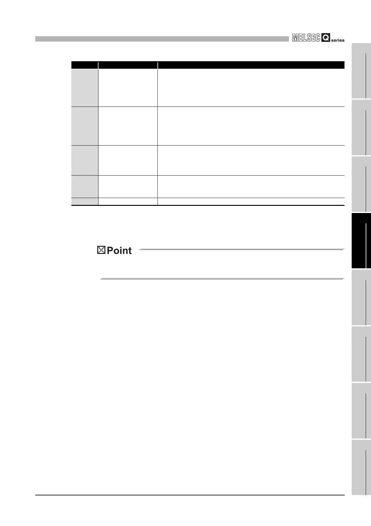
Number Name and appearance Description
1)
RUN LED
*2
Displays the operating status of the A/D converter module.
On :
Flashing :
Off :
Normal operation
During offset/gain setting mode
5V power supply interrupted, watchdog timer error occurred, or
online module change enabled.
2) ERR. LED
Displays the error status of the A/D converter module.
On :
Flashing :
Off :
Error
*1
Error in switch settings. Switch No. 5 of the intelligent function
module has been set to a value other than zero.
Normal operation
3) ALM LED
Displays the alarm status of the A/D converter module.
On :
Flashing :
Off :
An alarm (process alarm, rate alarm) occurred.
An input signal error occurred.
Normal operation
4)
FG terminal L-Shaped
metal fitting (Q66AD-DG
only)
Metal fitting to wire for FG of the Q66AD-DG.
5) Serial No. display Displays the serial No. of the A/D converter module.
 Loading...


