3
SPECIFICATIONS
3.4 Buffer Memory
3.4.1 Buffer memory assignment
3 - 54
1
OVERVIEW
2
SYSTEM
CONFIGURATION
3
SPECIFICATIONS
4
SETUP AND
PROCEDURES
BEFORE OPERATION
5
UTILITY PACKAGE
(GX CONFIGURATOR-
AD)
6
PROGRAMMING
7
ONLINE MODULE
CHANGE
8
TROUBLESHOOTING
*1 Indicates whether reading from and writing to a sequence program are enabled.
R : Read enabled
W : Write enabled
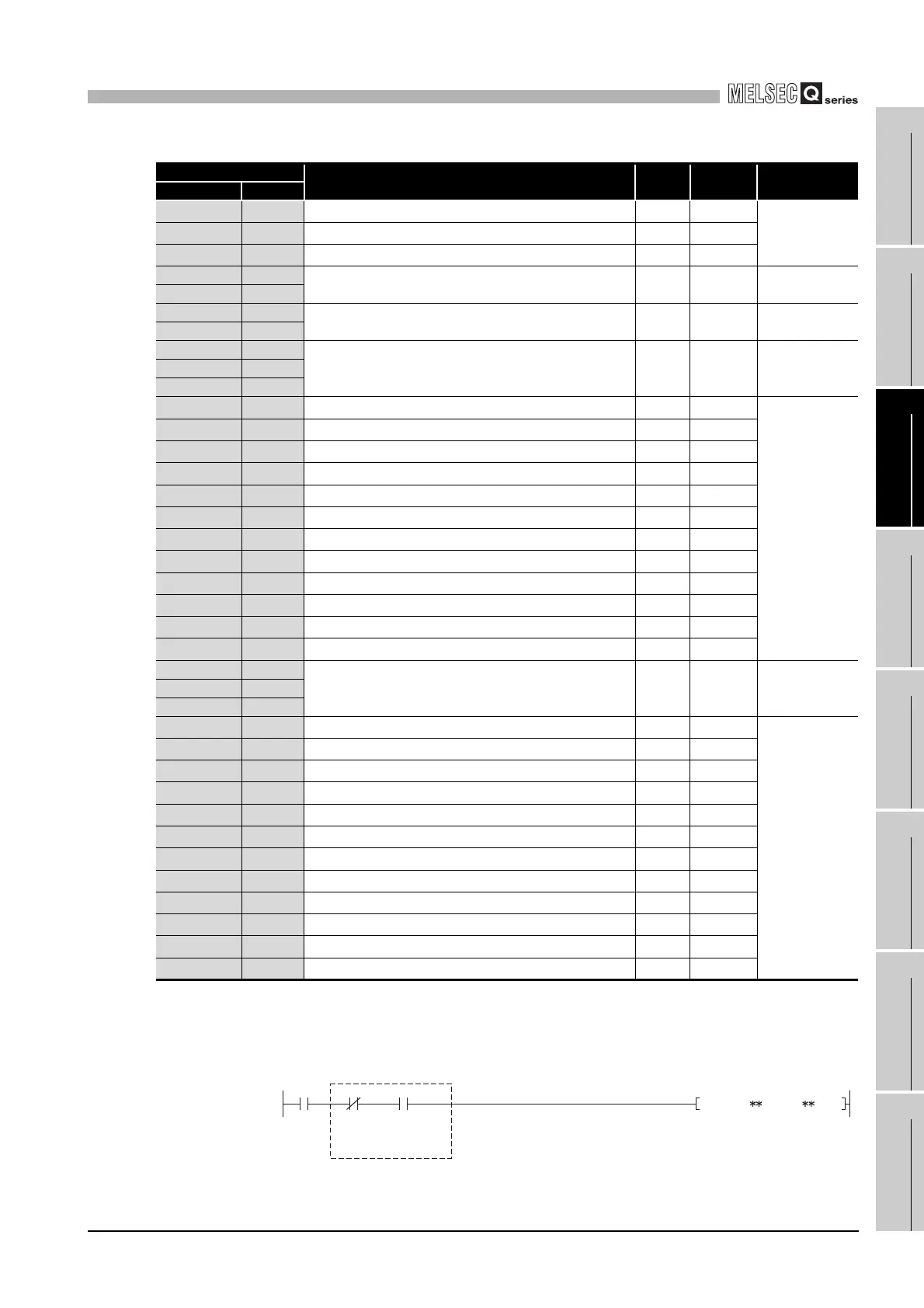
*2 When writing data to the buffer memory, always use the interlock condition (buffer memory write
condition) of the following I/O signals.
*3 Areas used to restore the User range settings offset/gain values when the module is replaced
online.
Refer to Chapter 7 for details of online module change.
Table3.9 Buffer memory assignment of Q66AD-DG (5/5)
Address
Description Default
R/W
*1
Reference
Hexadecimal Decimal
99H 153 CH4 Input signal error detection upper limit setting value 50
R/W
*2
Section 3.4.229AH 154 CH5 Input signal error detection upper limit setting value 50
R/W
*2
9BH 155 CH6 Input signal error detection upper limit setting value 50
R/W
*2
9CH 156
System area — — —
9DH 157
9EH 158
Mode switching setting 0 R/W Section 3.4.23
9FH 159
A0H 160
System area — — —
to to
C9H 201
CAH 202
CH1 Factory default offset value
*3
0R/W
Section 3.4.25
CBH 203
CH1 Factory default gain value
*3
0R/W
CCH 204
CH2 Factory default offset value
*3
0R/W
CDH 205
CH2 Factory default gain value
*3
0R/W
CEH 206
CH3 Factory default offset value
*3
0R/W
CFH 207
CH3 Factory default gain value
*3
0R/W
D0H 208
CH4 Factory default offset value
*3
0R/W
D1H 209
CH4 Factory default gain value
*3
0R/W
D2H 210
CH5 Factory default offset value
*3
0R/W
D3H 211
CH5 Factory default gain value
*3
0R/W
D4H 212
CH6 Factory default offset value
*3
0R/W
D5H 213
CH6 Factory default gain value
*3
0R/W
D6H 214
System area — — —
to to
D9H 217
DAH 218
CH1 User range settings offset value
*3
0R/W
Section 3.4.25
DBH 219
CH1 User range settings gain value
*3
0R/W
DCH 220
CH2 User range settings offset value
*3
0R/W
DDH 221
CH2 User range settings gain value
*3
0R/W
DEH 222
CH3 User range settings offset value
*3
0R/W
DFH 223
CH3 User range settings gain value
*3
0R/W
E0H 224
CH4 User range settings offset value
*3
0R/W
E1H 225
CH4 User range settings gain value
*3
0R/W
E2H 226
CH5 User range settings offset value
*3
0R/W
E3H 227
CH5 User range settings gain value
*3
0R/W
E4H 228
CH6 User range settings offset value
*3
0R/W
E5H 229
CH6 User range settings gain value
*3
0R/W
Writing
request
Y9 X9
Operating
condition
setting
completed
flag
Operating
condition
setting
request
Buffer memory writing condition
MOV
 Loading...


