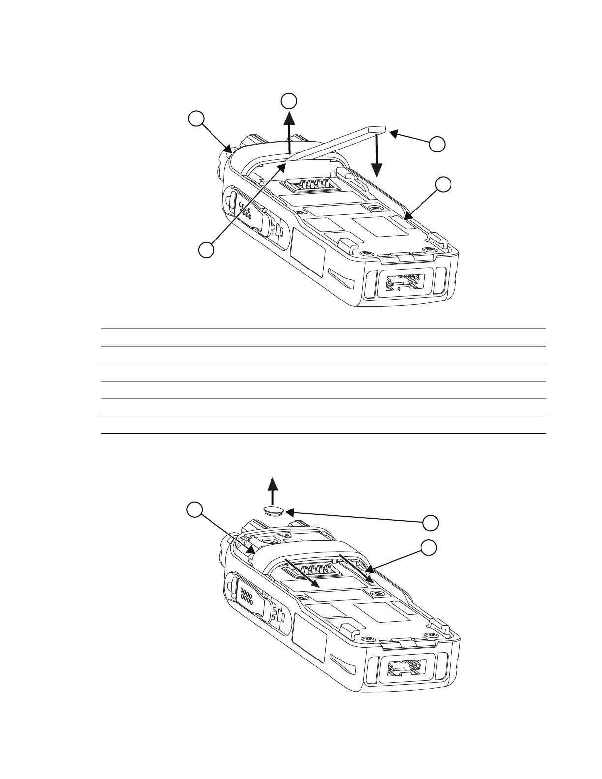
Figure 23: Removing the Back Cover
No. Description
1 Pry the Back Cover upwards
2 Back Cover
3 Slot in between Back Cover and Back Chassis
4 Black Stick/Flat-tip screwdriver
5 Back Chasis
3. Remove the RF Switch Seal from the Back Chassis.
Figure 24: Removing the RF Switch Seal
68015000841-EL
Chapter 5: Maintenance
97
 Loading...