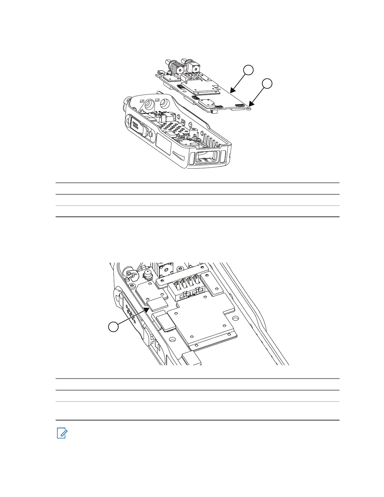
Figure 41: Main Board Installation
No. Description
1 Main board
2 PCB Guide hole
4. Carefully connect all flex connectors to the main board.
5. Place the thermal pad on top of the head spreader on the main board. Make sure it is aligned properly
with the head spreader.
Figure 42: Thermal Pad Installation
No. Description
1 Thermal pad
2 Place the thermal pad on top of the head
spreader at this position.
NOTE: Note: Replace the thermal pad after every service. Do not reuse the outdated pad.
6. Using the Torx driver with the 6IP Torx-Plus bit, screw the two screws with a torque of 2.5±0.1 in-lb
(0.28±0.011 Nm).
68015000841-EL
Chapter 5: Maintenance
114

 Loading...