Bottom Connector Pin BTB Connector Pin, J1200 Signal
7 26, 28 SWB+_SUPPLY
12 2, 4, 6, 8, 10, 12 EXTB+
15 16 BOOT_MODE
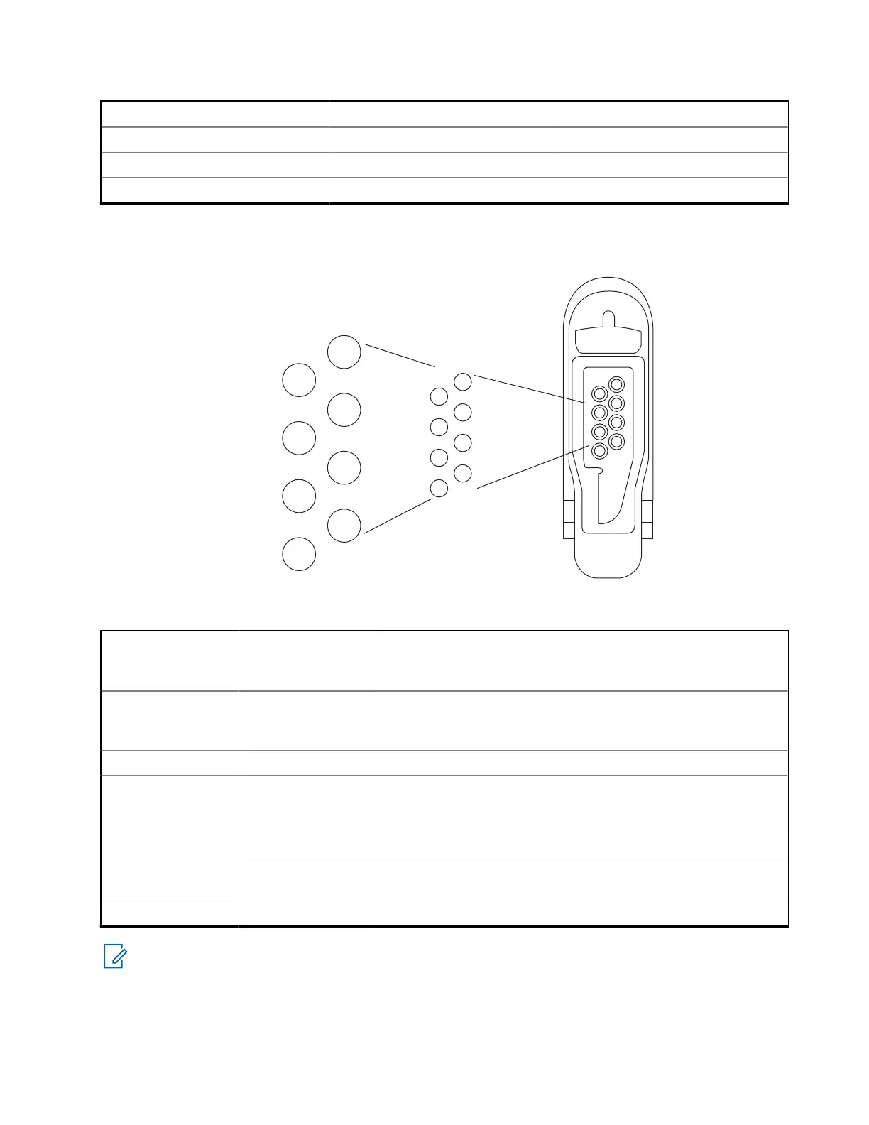
SLIM Connector and FuG Terminals
Figure 54: SLIM Connector
2
4
6
8
1
3
5
7
1
3
5
7
2
VSUP
USB_VBUS
VIBRA_ALERT
SPKR+
LINEOUT+
SPKR+
LINEOUT-
GND
DETECT/1-WIRE/PTT
USB_D+
UART_TXD
MIC-
MIC+
RES_MEAS
GPIO
USB_D-
UART_RXD
4
6
8
Table 46: SLIM Side Audio UC – Modes of Operation
Pin Empty States Default State
(Spkr & Mic)
"RSM"
Default State
(Spkr only) "Ear-
piece"
IMPRES State
"RSM/Earpiece"
VSUP |
USB_VBUS | VI-
BRA_ALERT
OFF (0 V) 5.0 V 5.0 V 5.0 V
GND 0 V 0 V 0 V 0 V
SPKR+ | LINE-
OUT+
ON (Default Pro-
file)
ON (Default Pro-
file)
ON (IMPRES Pro-
file)
SPKR- | LINE-
OUT-
OFF ON (Default Pro-
file)
ON (Default Pro-
file)
ON (IMPRES Pro-
file)
MIC+ OFF ON (Default Pro-
file)
OFF ON (IMPRES Pro-
file)
MIC- 0 V 0 V 0 V 0 V
NOTE: HIGH = Logic 1 = 2.775 V±10%, and LOW = Logic 0 = < 0.4 V
68015000841-EL
Appendix B: Bottom/GCAI Connector
139
 Loading...