6 Mounting
Maschinenfabrik Reinhausen GmbH 202070 6385142/08 ENETOS
®
ED
tions, turn another 8 A tap-change indicator sections in the same direc-
tion (example: 8-4=4) to complete the tap-change operation. Then turn in
the opposite direction until the indicator is in the mid-position of the area
marked in gray on the tap-change indicator. Check the coupling again as
described previously.
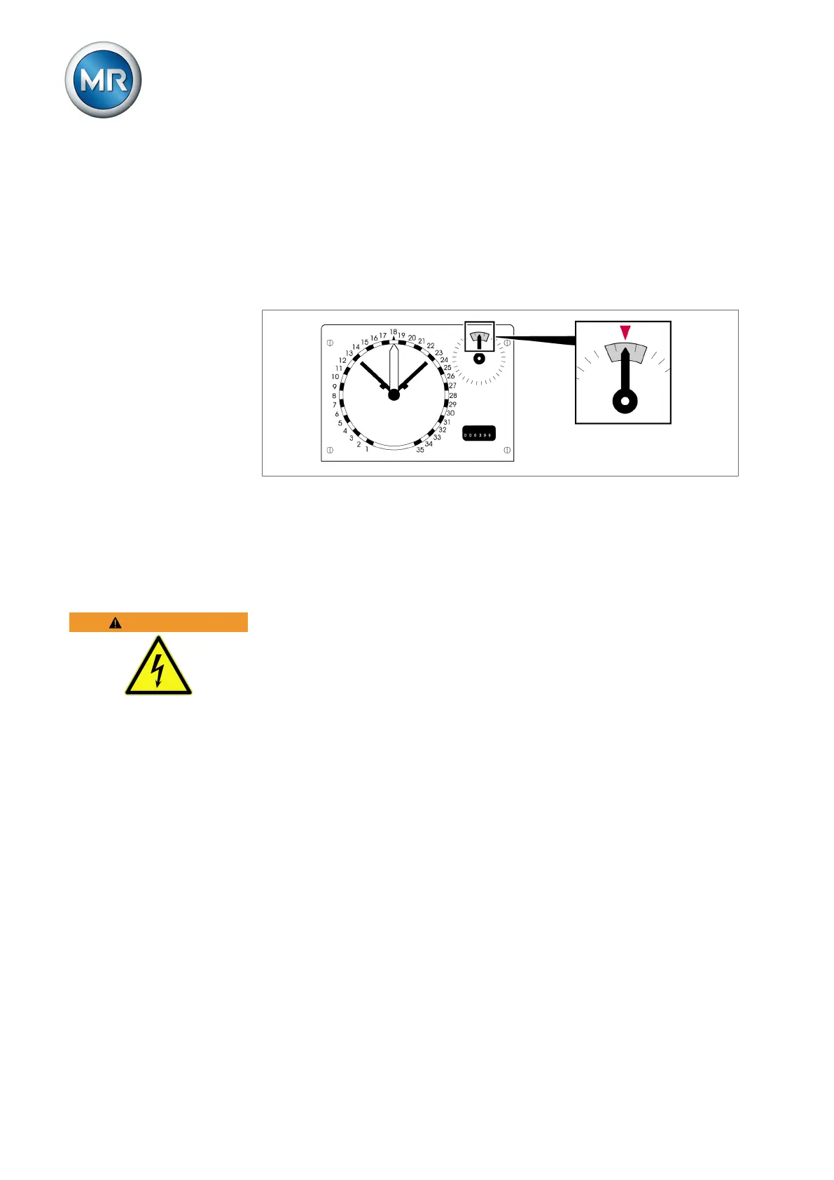
17. The pointer of the tap-change indicator must be in the mid-position of the
area marked in gray once the on-load tap-change operation with the
hand crank is complete.
Figure51: Pointer in the mid-position
18. Once coupling is complete in both directions, check by carrying out sev-
eral on-load tap-change operations and check that the on-load tap-
changer and motor-drive unit are in the same tap position.
6.4 Connecting the ISM® assemblies
WARNING
Electric shock!
Risk of fatal injury due to connection errors.
► Ground the device using the grounding screw on the housing.
6.4.1 Cable recommendation (ISM® assemblies)
Please note the following Maschinenfabrik Reinhausen GmbH recommenda-
tion when wiring the device.
▪ Excessive line capacitance can prevent the relay contacts from interrupt-
ing the contact current. In control circuits operated with alternating current,
take into account the effect of the line capacitance of long control cables
on the function of the relay contacts.
▪ If you want to route Ethernet connections from a control cabinet or build-
ing, we recommend using fiber-optic cables (in accordance with the
IEC61850-90-4 recommendation).
▪ Ensure that the copper cables used have a temperature resistance of
70°C.