6 Mounting
Maschinenfabrik Reinhausen GmbH 202078 6385142/08 ENETOS
®
ED
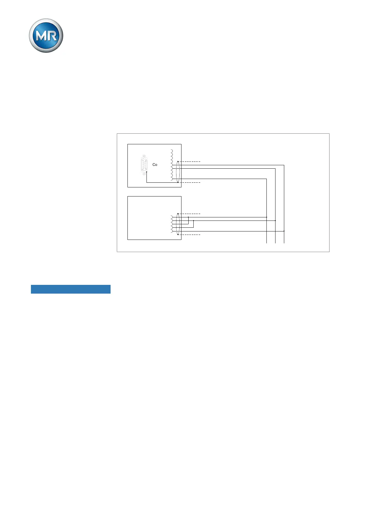
6.4.3.4 MSENSE®-FO ECU-I/S
If you would like to use an MSENSE®-FO ECU-I or ECU-S sensor, you must
connect the sensor to the RS485 plug terminals on the sensor bus. Use a
shielding clamp to apply the shield to the cable. If the MSENSE®-FO sensor
is the only bus device or the last bus device, you must use a terminating re-
sistor (120Ω, 0.5W). You must activate the half-duplex, 2-conductor operat-
ing mode on the sensor via the MSET-FO configuration software.
CPU-COM2
MSENSE®-FO
D0 (A)
D1 (B)
Com. (C)
1
2
3
4
5
6
7
8
9
Tx+ 1
2
3
4
5
Tx-
Rx+
Rx-
GND
Figure62: Connection example MSENSE®-FO ECU-I and ECU-S (terminal RS485)
6.4.4 Information about connecting analog sensors
NOTICE
Damage to the device and sensors!
Incorrectly connected and configured analog inputs/outputs may result in
damage to the device and sensor.
► Follow information about connecting analog sensors [►Section 6.4.4,
Page 78].
► Configure analog inputs and outputs according to the connected sensors.